Camshafts and camshaft adjusters, removing and installing: Installing
WARNING: This page is about a different car, the 2006 Audi A4, 2005 Audi A4, 2004 Audi A4, 2003 Audi A4, and 2002 Audi A4. However, it is still accessible from the selected car via links, so may be relevant.
NOTE:
Replace gaskets and O-rings.
- Crankshaft aligned using T40026 locking pin
- Oil camshaft journal surface.
Left cylinder head
- Insert camshaft into cylinder head as depicted in illustration.
- Cams at cylinder 5 point downward evenly (arrows).
Right cylinder head
- Insert camshaft into cylinder head as depicted in illustration.
- Cams at cylinder 3 point upward evenly (arrows)
All
- Cut tube nozzle at front marking (jet diameter approx. 1 mm).
NOTE:
Sealant bead must be applied according to exact specifications, otherwise excess sealant could get into the camshaft bearings.
- Apply sealant to clean sealing surface of guide frame as depicted in illustration.
- Thickness of sealant bead: Approx. 1.2 mm
- Distance of sealant bead to camshaft bearings at specified locations -1- to -8-: at least 5 mm
- In addition, sealing surfaces around spark plug holes obtain a sealant ring each, -9- to -11-
- Immediately set guide frame in place and align using T40029 locating pin.
NOTE:
- Setting in place and tightening the guide frame should occur without interruptions since the sealant starts to harden immediately.
- After installing guide frame, allow sealant to dry for approx. 30 minutes.
- Tighten bolts of guide frame in sequence of numbers and follow arrows uniformly by hand.
- Guide frame must make full contact with cylinder head surface
- Tighten bolts of guide frame to final tightening torque (10 Nm).
- Using T10055 extractor, remove T40029 locating pin from cylinder head.
Left cylinder head
- Insert T40030 camshaft adjuster gauge at camshafts.
- Spread T40030 camshaft adjuster gauge with threaded shaft (tightening torque 10 Nm) until it is seated without axial play.
Right cylinder head
- Install camshaft gear of exhaust camshaft.
- Turn exhaust camshaft (arrow -1-) and intake camshaft (arrow -2-) 30° in direction of arrow at same time...
Fig 10: Turning Engine Until Cams At Intake And Exhaust Camshaft Of Cylinder 3 (Right Cylinder Bank) Point Upward Uniformly
- ..until cams (arrows) of cylinder 3 at intake and exhaust camshafts are as shown in illustration.
- Insert T40030 camshaft adjuster gauge at camshafts.
- Remove exhaust camshaft gear again.
All
- Install Camshaft Position (CMP) sensor housing and tighten bolts -1- to -6-.
- Check whether piston rings at camshafts are installed and whether piston ring ends are engaged with each other.
NOTE:
If ends of installed piston are not of the locking type (cannot be locked together):
- Always orient the rings so that the gaps (of all three rings) are at the top of the camshaft prior to installation of the camshaft adjustment housing.
With all ring gaps aligned at the top of camshaft:
- Install camshaft adjustment housing using a gentle side to side motion (do not rock top to bottom).
- If necessary, engage ends of installed piston rings (arrows), as depicted in illustration.
NOTE:
 Courtesy of VOLKSWAGEN UNITED STATES, INC.
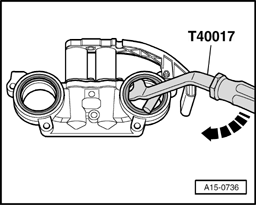
If the camshaft sealing rings are being replaced, they must be removed from camshaft adjustment housing before installation, using T40017 lever. Installing camshaft sealing rings. Refer to Camshaft oil seals, replacing .
If the camshaft sealing rings are being replaced, they must be removed from camshaft adjustment housing before installation, using T40017 lever. Installing camshaft sealing rings. Refer to Camshaft oil seals, replacing .
- Install camshaft adjustment housing and tighten bolts -1- to -6-.
Installation is reverse of removal, noting the following:
- Install combination valve for Secondary Air Injection. Refer to Left combination valve for secondary air injection, removing and installing or Right combination valve for secondary air injection, removing and installing .
- Install toothed belt (adjust timing). Refer to Installing (adjusting valve timing) .
NOTE:
- After installing camshafts, do not start engine for at least 30 minutes. The hydraulic valve lifters have to settle (otherwise valves will strike the pistons).
- After working on the valvetrain, carefully rotate engine by hand at least 2 full revolutions to ensure that valves do not strike the pistons when starting.