Air Mix Door Actuator: Wiring Diagram
WARNING: This page is about a different car, the 2012 Subaru Forester. However, it is still accessible from the selected car via links, so may be relevant.
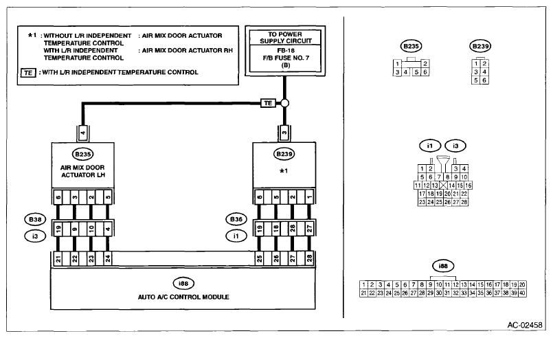 Courtesy of SUBARU OF AMERICA, INC.
 DIAGNOSTIC PROCEDURE CHART
| Step |
Check |
Yes |
No |
1 CHECK POWER SUPPLY OF AIR MIX DOOR ACTUATOR.
- Turn the ignition switch to OFF.
- Disconnect the air mix door actuator connector.
- Turn the ignition switch to ON.
- Measure the voltage between the air mix door actuator connector terminal and chassis ground.
Connector & terminal
Without left/right independent air conditioner
(B239) No. 3 (+) - Chassis ground (-):
With left/right independent air conditioner
(B235) No. 4 (+) - Chassis ground (-):
(B239) No. 3 (+) - Chassis ground (-):
|
Is the voltage approx. 10 V or more? |
Go to step 2
. |
Check the DC power supply circuit. |
2 CHECK AIR MIX DOOR ACTUATOR.
- Turn the ignition switch to OFF.
- Measure the resistance between air mix actuator terminals using a tester.
Connector & terminal
Without left/right independent air conditioner
(B239) No. 3 - No. 1:
(B239) No. 3 - No. 2:
(B239) No. 3 - No. 5:
(B239) No. 3 - No. 6:
With left/right independent air conditioner
(B235) No. 4 - No. 2:
(B235) No. 4 - No. 3:
(B235) No. 4 - No. 5:
(B235) No. 4 - No. 6:
(B239) No. 3 - No. 1:
(B239) No. 3 - No. 2:
(B239) No. 3 - No. 5:
(B239) No. 3 - No. 6:
|
Is the resistance 80 - 100 Ω? |
Go to step 3
. |
Replace the air mix door actuator. |
3 CHECK HARNESS BETWEEN AUTO A/C CONTROL MODULE AND AIR MIX DOOR ACTUATOR.
- Disconnect the auto A/C control module connector.
- Measure the resistance between auto A/C control module and air mix door actuator connector.
Connector & terminal
Without left/right independent air conditioner
(B239) No. 1 - (i88) No. 28:
(B239) No. 2 - (i88) No. 27:
(B239) No. 5 - (i88) No. 26:
(B239) No. 6 - (i88) No. 25:
With left/right independent air conditioner
(B235) No. 2 - (i88) No. 23:
(B235) No. 3 - (i88) No. 22:
(B235) No. 5 - (i88) No. 24:
(B235) No. 6 - (i88) No. 21:
(B239) No. 1 - (i88) No. 28:
(B239) No. 2 - (i88) No. 27:
(B239) No. 5 - (i88) No. 26:
(B239) No. 6 - (i88) No. 25:
|
Is the resistance less than 1 Ω? |
Go to step 4
. |
Repair the harness between auto A/C control module and air mix door actuator. |
4 CHECK FOR POOR CONTACT.
Check poor contact of auto A/C control module and connector. |
Is there poor contact of connector? |
Repair the connector. |
Replace the auto A/C control module. < Ref. to
REMOVAL
, Control Unit (Auto A/C Model). > |