Steering Column Overview
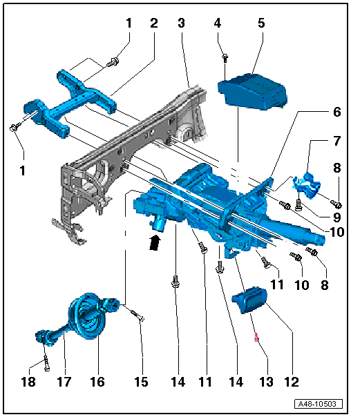 Courtesy of AUDI OF AMERICA, LLC
- Bolt
- Mounting Bracket
- Central Tube
- Bolt
- Electronic Steering Column Lock Control Module -J764-
- Installed on vehicles with lock locking system.
- Removing and installing, refer to ELECTRONIC STEERING COLUMN LOCK CONTROL MODULE -J764- .
- If the module was replaced, the following work must performed using the vehicle diagnostic tester. Select the program in "Guided Functions" and follow the prompts on the screen.
- Steering Column
- Depending on the version of the steering (with or without dynamic steering) different versions of the steering columns are installed. Refer to the Parts Information.
- Actuator -arrow- installed on vehicles with dynamic steering.
- The actuator -arrow- must not be loosened or separated from the steering column.
- The actuator and the steering column are one component; they are replaced together. Refer to the Parts Information.
- The actuator -arrows- has a "safety lock for the active steering" (locking magnet).
- "Safety lock for active steering" (locking magnet), removing and installing, refer to ACTIVE STEERING SAFETY LOCK (LOCKING MAGNET) .
- If the steering column and adjuster were replaced, then it is necessary to perform a basic setting on the dynamic steering. Refer to DYNAMIC STEERING BASIC SETTING
.
- Removing and installing, refer to STEERING COLUMN .
- Check for damage. Refer to STEERING COLUMN, CHECKING FOR DAMAGE .
- Right Knee Bar
- Installed depending on the country version.
- Bolt
- 20 Nm
- 22 Nm on the Cabriolet.
- Quantity: 2
- Depending on the country version, the knee bar is bolted on the right driver side.
- Follow the assembly sequence when installing. Refer to INSTALLING .
- Bolt
- Bolt
- 20 Nm
- Quantity: 2
- Follow the assembly sequence when installing. Refer to INSTALLING .
- Bolt
- 20 Nm
- Quantity: 2
- Follow the assembly sequence when installing. Refer to INSTALLING .
- Handle
- Bolt
- Bolt
- 20 Nm
- Quantity: 2
- Follow the assembly sequence when installing. Refer to INSTALLING .
- Bolt
- 30 Nm + 90° turn
- Always replace if removed.
- The threaded hole for the bolt must always be cleaned (for example, using a thread tap).
- Protective Boot
- Align the positioning arrow to the "12 o'clock position".
- Steering Intermediate Shaft
- Bolt
- 30 Nm + 90° turn
- Always replace if removed.
- The threaded hole for the bolt must always be cleaned (for example, using a thread tap).