Removal & Installation (Aluminum)
- Remove wheel cover. Loosen drive axle bolt by 90° only. Raise and support vehicle. Remove wheel. Remove drive axle bolt completely. On vehicles equipped with an outer joint of 98 mm diameter, drive axle must be removed. See AXLE SHAFTS - FRONT & REAR
article in DRIVELINE/AXLES.
- Remove brake caliper bolts. Wire brake caliper aside without disconnecting brake hose. Remove brake disc. Remove socket-head bolt (1). See Fig 1
. Remove ABS wheel speed sensor (2) from wheel bearing housing. Remove anti-roll bar link bolt from lower control arm.
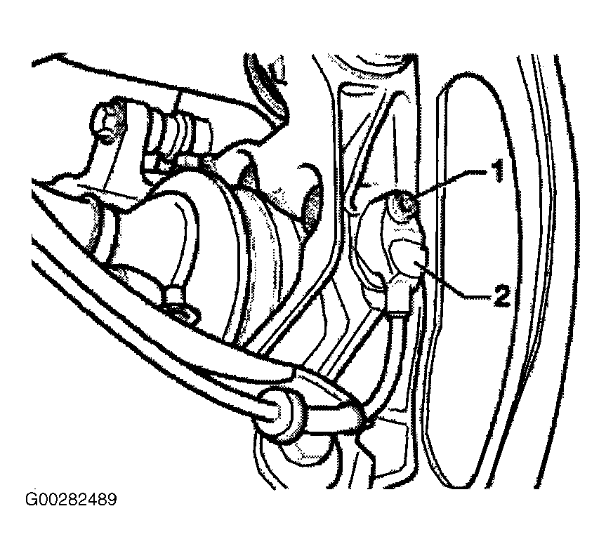 Courtesy of VOLKSWAGEN UNITED STATES, INC.
- Unscrew bolt (A) for tie rod. See Figure
. Mark installation position of eccentric washer for bolt (B). Unscrew bolt (B).
- Remove upper control arm-to-wheel bearing housing. pull wheel bearing housing off drive axle shaft.
- Installation is the reverse of removal procedure. Bonded rubber bushings can only be turned to a limited extent. Bolted connections should only be tightened when vehicle is standing on ground. Tighten all nuts and bolts to specification. See TORQUE SPECIFICATIONS
.