Audio System Description
Audio System Description
Overview
The audio unit acts as the processor for all audio functions. You can select the audio functions from the audio panel, the audio remote (on steering wheel), or by using the navigation voice control system. The audio display provides the current front and rear audio status. For vehicles with the navigation option, additional audio information is available by touching the audio button. (See the owner's manual for more details.)
Each audio component passes its audio or audio signal to the audio unit. In addition, it communicates with the audio unit via the GA-Net bus. Any open connection in this circuit will cause audio and navigation functions to appear inoperative.
The audio unit has a built-in EEPROM (electrically erasable programmable read-only memory). This memory holds the audio presets data (AM/FM radio frequency, sound settings, etc.) even when the battery is disconnected.
With the ELS and the premium sound system, an audio amplifier unit powers the speakers.
The 6 DVD (6 CD) changer output can be directed to the audio unit.
The XM can be output to either the front or the RES (rear entertainment system). However, if the XM is playing in the front, the CD changer cannot be used for the RES. The RES (built into the audio unit) can be used to play a CD in the rear.
A security signal is daisy-chained between the audio, RES and navigation components for integration into the vehicle's alarm system.
Speed-sensitive volume compensation (SVC)
Some audio systems are equipped with speed-sensitive volume compensation (SVC). The navigation or audio unit receives the vehicle speed pulse (VSP) from the PCM. The system processes the speed input and increases the navigation or audio system volume level as the vehicle speed increases to compensate for the various interior noise that occurs at higher speeds. When the vehicle slows down, the volume returns to its normal level. The SVC has four settings: SVC OFF, LOW, MID, and HIGH that can be adjusted using the navigation or audio unit. The SVC comes from the factory with the MID set as the default.
To change the audio unit SVC setting, press the tune folder sound knob repeatedly until the SVC is displayed, rotate the knob to adjust the SVC to the desired setting (SVC OFF, LOW, MID, or HIGH).
To change the navigation unit SVC setting, press the AUDIO button, and then select the SOUND icon on the navigation display. Press the navigation display to select the desired setting (OFF, LOW, MID, HI).
Overview
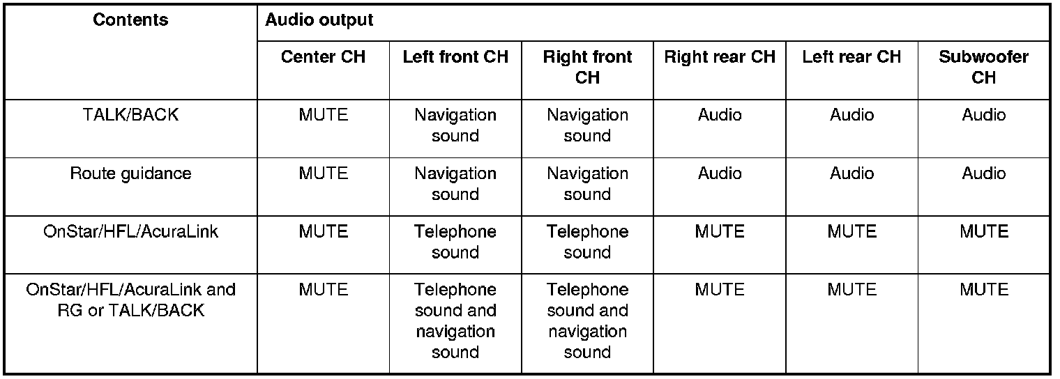
The optional navigation system provides voice control for radio, XM, CD player, and RES functions. The GA-Net (audio unit) communicates the voice control commands. When using the TALK/BACK or route guidance (RG), only the center speaker is muted and you hear the navigation instructions through the front speakers. When using HFL/AcuraLink, the center speaker, the rear speakers, and the subwoofer are muted and the front speakers give the telephone sound. When using HFL/AcuraLink and RG or TALK/BACK, the center speaker, the rear speakers, and the subwoofer are muted and you hear the telephone sound and navigation instructions through the front speakers but not the RES headphones. GA-Net bus passes the muting commands. For more information, see the navigation section. The outline of the audio interruption function is shown in the following table.
System Diagram
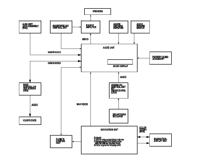
NOTE: All items may not apply to this vehicle. See the Owner's Manual for more information.
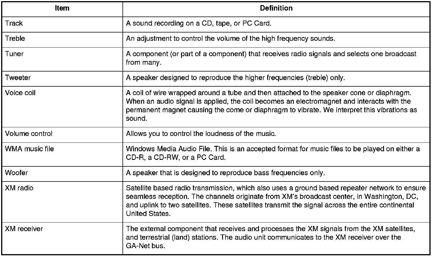
Audio Glossary
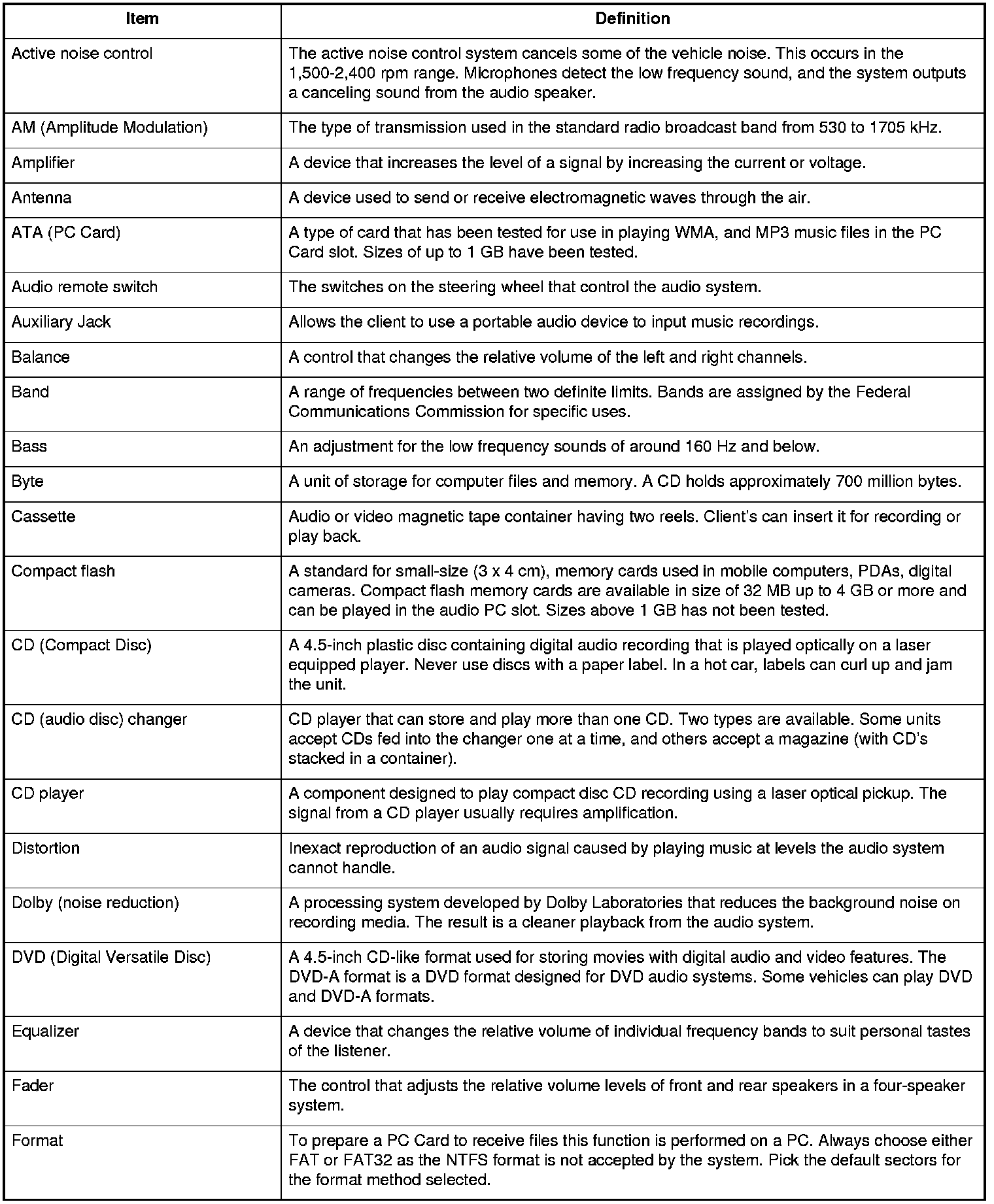

Audio Glossary
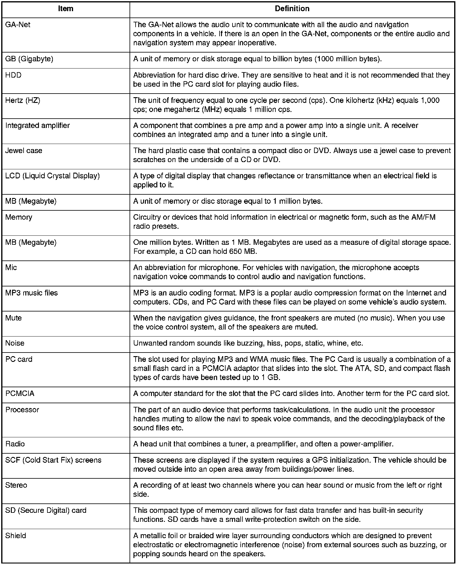

Audio Glossary
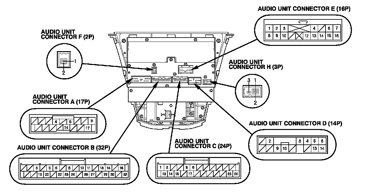
Audio Unit Connector for Inputs and Outputs
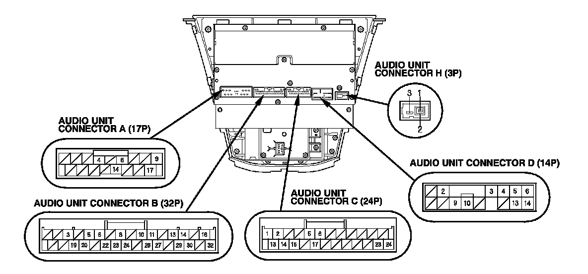
When replacing an audio unit connector, match the wires to the cavities listed in the following tables.
With navigation/With rear entertainment system
With navigation/Without rear entertainment system
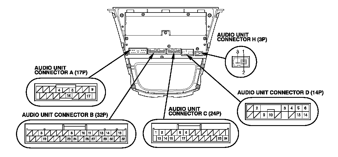
Audio Unit Connector for Inputs and Outputs
When replacing an audio unit connector, match the wires to the cavities listed in the following tables.
Without navigation/Without rear entertainment system
AUDIO UNIT CONNECTOR A (17P)

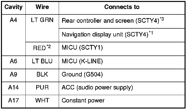
*1: With navigation
*2: Without navigation
*3: With rear entertainment
AUDIO UNIT CONNECTOR B (32P)
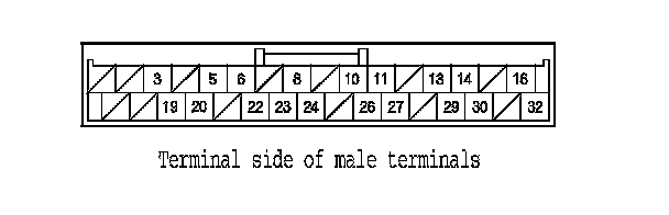
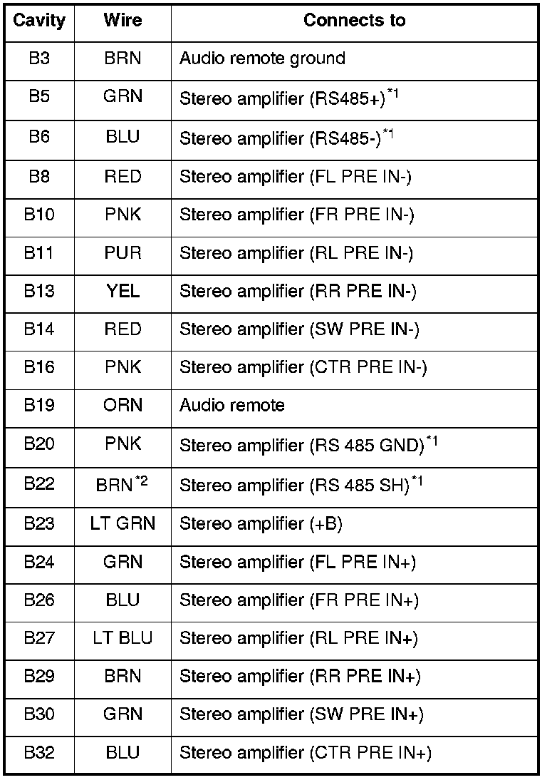
*1: With navigation
*2: The shielded wires have a heat-shrunk tube insulating the outside of the wire. The color of the insulating tube, typically black or dark gray, may not match the color of the wire listed on the schematic.
AUDIO UNIT CONNECTOR C (24P) (With rear entertainment)
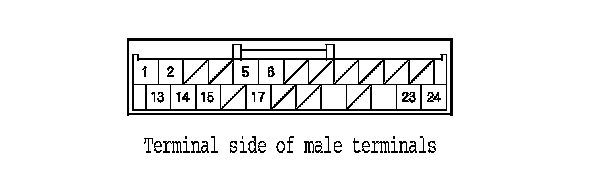
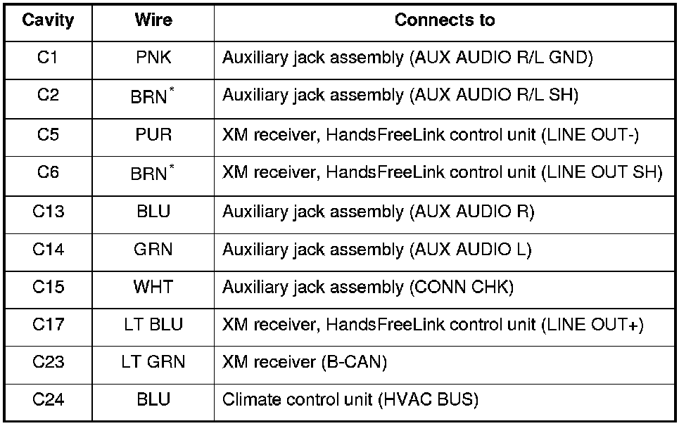
*: The shielded wires have a heat-shrunk tube insulating the outside of the wire. The color of the insulating tube, typically black or dark gray, may not match the color of the wire listed on the schematic.
AUDIO UNIT CONNECTOR C (24P) (Without rear entertainment)
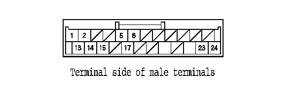
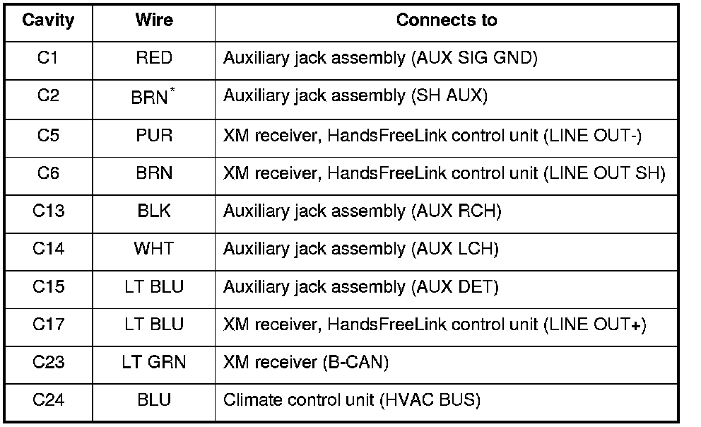
*: The shielded wires have a heat-shrunk tube insulating the outside of the wire. The color of the insulating tube, typically black or dark gray, may not match the color of the wire listed on the schematic.
AUDIO UNIT CONNECTOR D (14P)

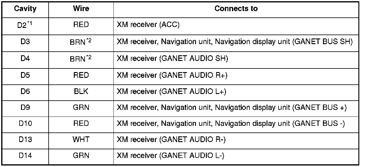
*1: Without AcuraLink
*2: The shielded wires have a heat-shrunk tube insulating the outside of the wire. The color of the insulating tube, typically black or dark gray, may not match the color of the wire listed on the schematic.
AUDIO UNIT CONNECTOR E (16P)
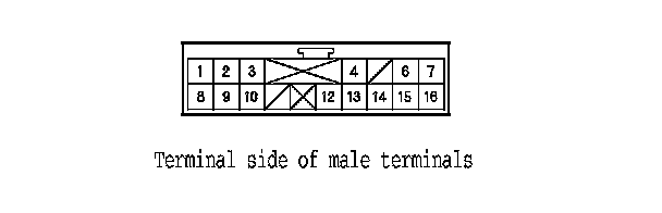
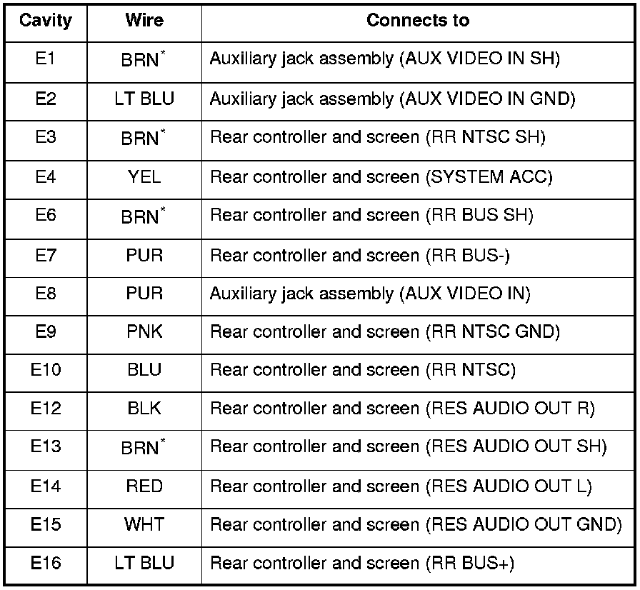
*: The shielded wires have a heat-shrunk tube insulating the outside of the wire. The color of the insulating tube, typically black or dark gray, may not match the color of the wire listed on the schematic.
AUDIO UNIT CONNECTOR F (2P)

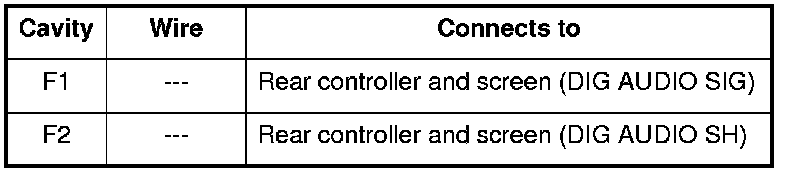
AUDIO UNIT CONNECTOR H (3P)

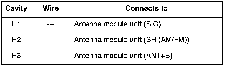
Stereo Amplifier Connector for Inputs and Outputs
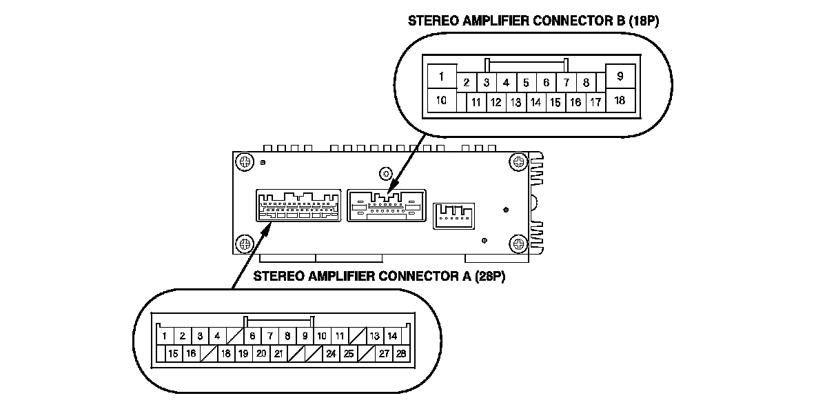
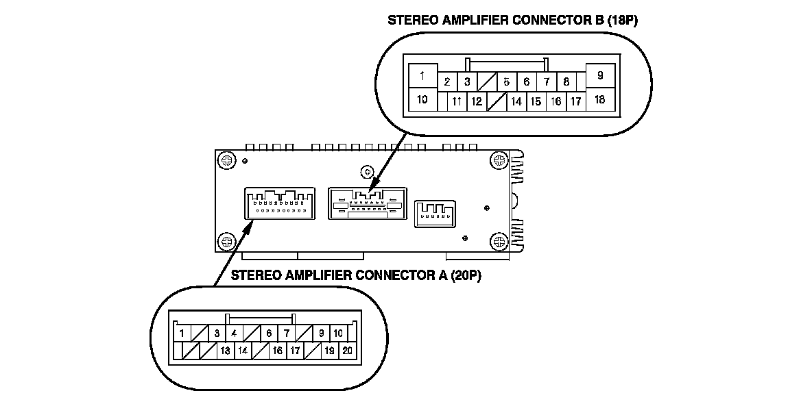
When replacing a stereo amplifier connector, match the wires to the cavities listed in the following tables.
With navigation
Without navigation
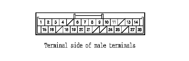
STEREO AMPLIFIER CONNECTOR A (28P) (With navigation)
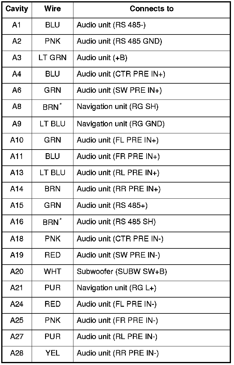
*: The shielded wires have a heat-shrunk tube insulating the outside of the wire. The color of the insulating tube, typically black or dark gray, may not match the color of the wire listed on the schematic.
STEREO AMPLIFIER CONNECTOR A (20P) (Without navigation)
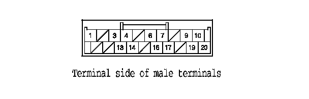
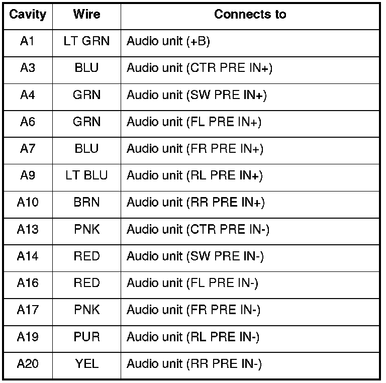
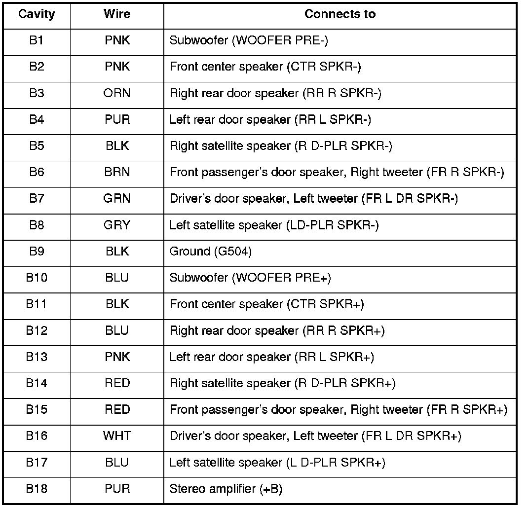
STEREO AMPLIFIER CONNECTOR B (18P) (With navigation)

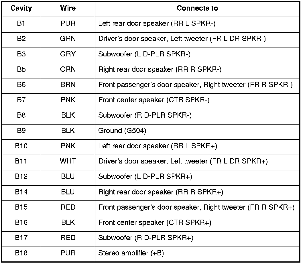
STEREO AMPLIFIER CONNECTOR B (18P) (Without navigation)

AcuraLink Control Unit (XM Receiver) Connector for Inputs and Outputs (With AcuraLink)
When replacing an AcuraLink Control Unit (XM receiver) connector, match the wires to the cavities listed in the following tables.
With AcuraLink
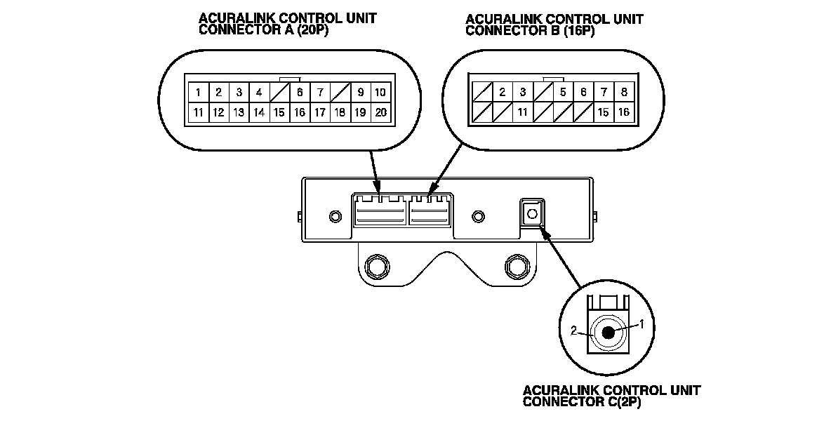
ACURALINK CONTROL UNIT CONNECTOR A (20P) (With navigation)

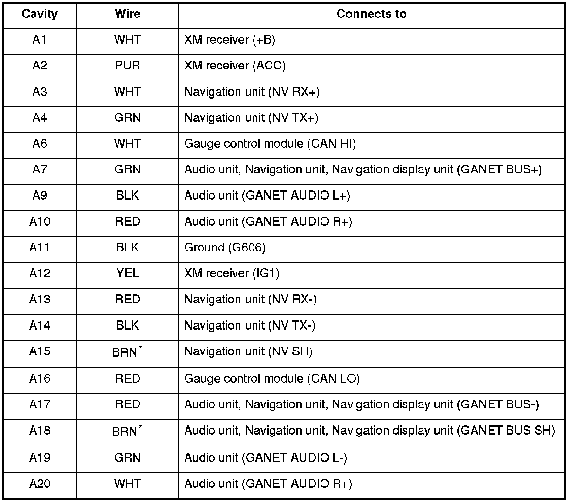
*: The shielded wires have a heat-shrunk tube insulating the outside of the wire. The color of the insulating tube, typically black or dark gray, may not match the color of the wire listed on the schematic.
ACURALINK CONTROL UNIT CONNECTOR B (16P) (With navigation)

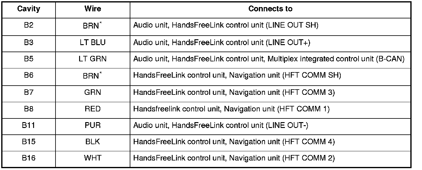
*: The shielded wires have a heat-shrunk tube insulating the outside of the wire. The color of the insulating tube, typically black or dark gray, may not match the color of the wire listed on the schematic.
XM Receiver Connector for Inputs and Outputs (Without AcuraLink)
When replacing an XM receiver connector, match the wires to the cavities listed in the following tables.
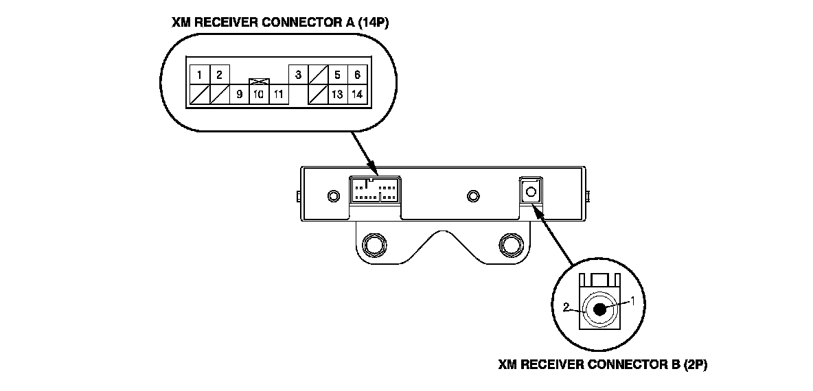
XM RECEIVER CONNECTOR A (14P) (without AcuraLink)
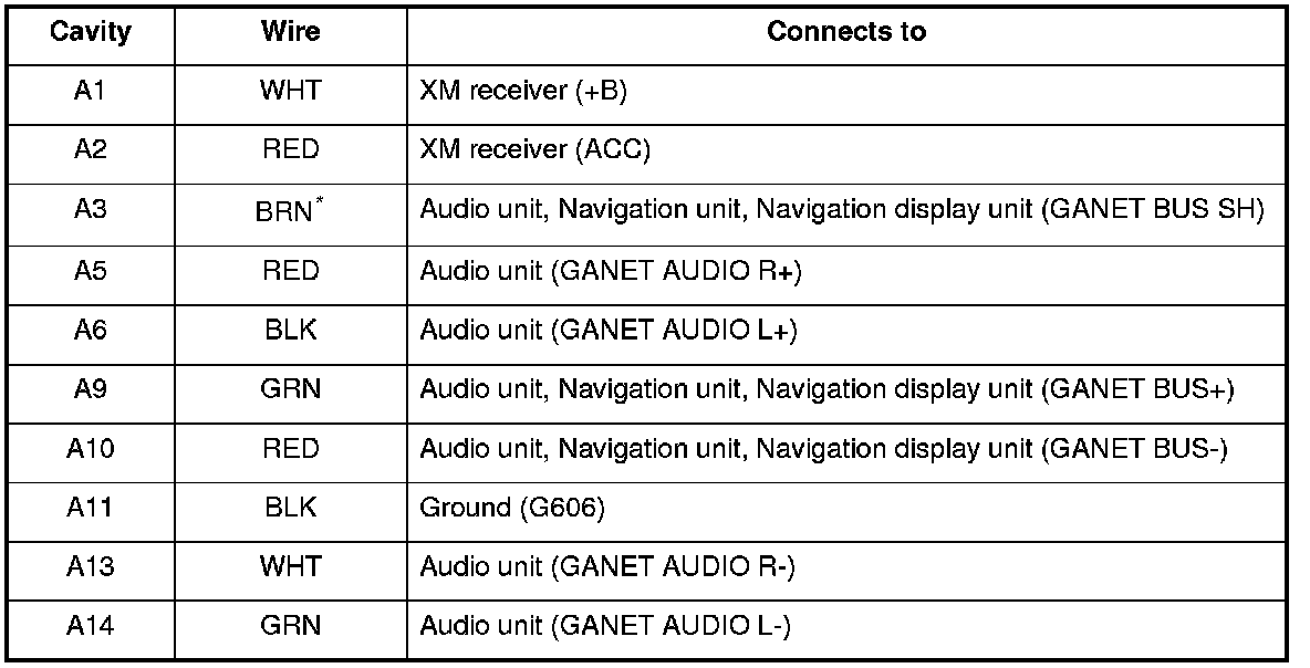
*: The shielded wires have a heat-shrunk tube insulating the outside of the wire. The color of the insulating tube, typically black or dark gray, may not match the color of the wire listed on the schematic.
Interface Dial Connector for Inputs and Outputs
When replacing an interface dial connector, match the wires to the cavities listed in the following table.
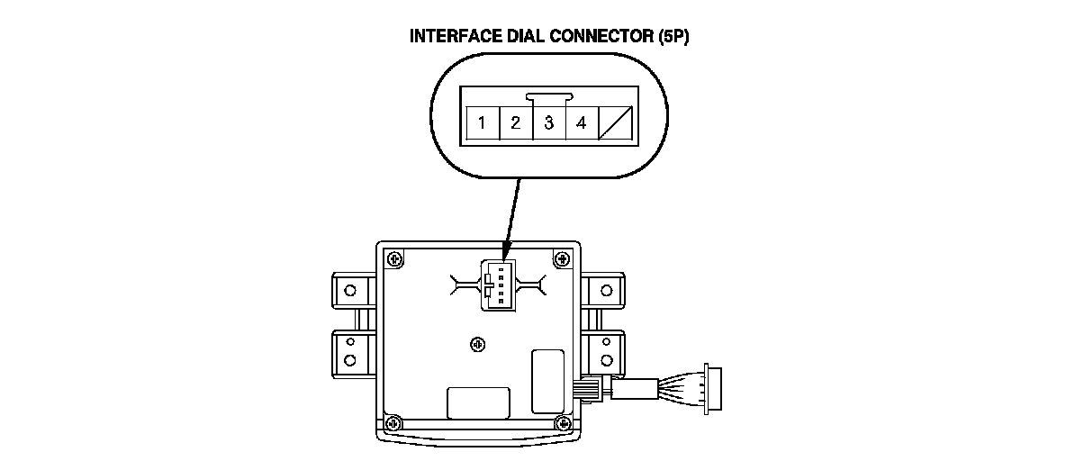
INTERFACE DIAL CONNECTOR (5P)
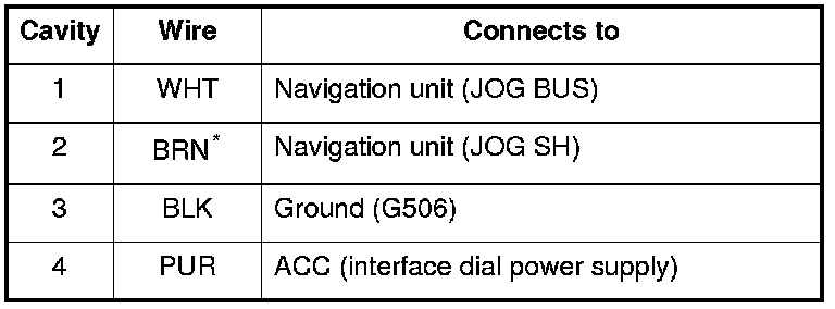
*: The shielded wires have a heat-shrunk tube insulating the outside of the wire. The color of the insulating tube, typically black or dark gray, may not match the color of the wire listed on the schematic.
Auxiliary Jack Assembly Connector for Inputs and Outputs (Without rear entertainment)
When replacing an auxiliary jack assembly connector, match the wires to the cavities listed in the following table.
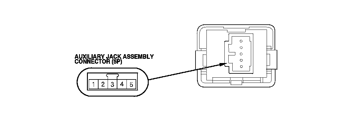
AUXILIARY JACK ASSEMBLY CONNECTOR (5P) (Without rear entertainment)
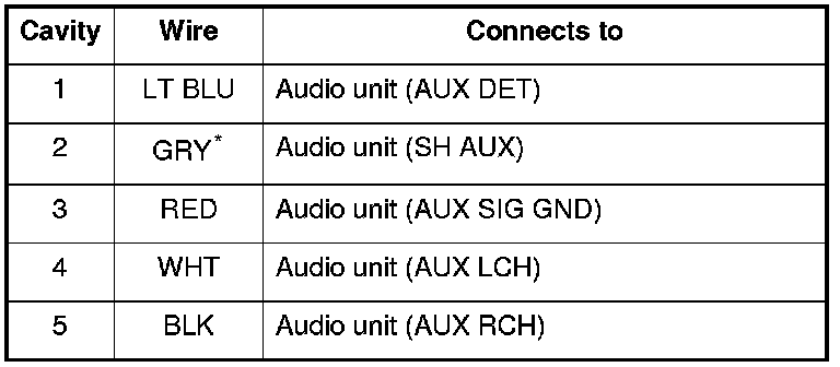
*: The shielded wires have a heat-shrunk tube insulating the outside of the wire. The color of the insulating tube, typically black or dark gray, may not match the color of the wire listed on the schematic.