DTC Troubleshooting
DTC Troubleshooting: P0721 (9), P0722 (9)
DTC P0721: Problem in Output Shaft (Countershaft) Speed Sensor Circuit
DTC P0722: Problem in Output Shaft (Countershaft) Speed Sensor Circuit (No Signal Input)
NOTE:
- Before you troubleshoot, record all freeze data and any on-board snapshot, and review General Troubleshooting Information. How to Troubleshoot A/T Systems
- This code is caused by an electrical circuit problem and cannot be caused by a mechanical problem in the transmission.
1. Clear the DTC with the HDS.
2. Raise the vehicle on a lift, make sure it is securely supported, and allow all four wheels to rotate freely.
3. Check for proper output shaft (countershaft) speed sensor installation. A/T Output Shaft (Countershaft) Speed Sensor Replacement If the sensor is installed improperly, correct problem, then go to step 37.
4. Start the engine. Run the vehicle in D with the engine speed at 2,000 rpm or higher, for at least 10 seconds.
5. Monitor the OBD STATUS for P0721 or P0722 in the DTCs/Freeze Data in A/T Mode Menu for a pass/fail.
Does the HDS indicate FAILED?
YES - Go to step 6.
NO - If the HDS indicates PASSED, intermittent failure, the system is OK at this time. Check for loose or poor connections at the PCM and output shaft (countershaft) speed sensor connectors. If the HDS indicates NOT COMPLETED, return to step 4 and recheck.
6. Turn the ignition switch to LOCK (0).
7. Jump the SCS line with the HDS.
8. Disconnect PCM connectors B (49P) and C (49P).
9. Check for continuity between PCM connector terminals B41 and body ground, and between C41 and body ground.
Is there continuity?
YES - Go to step 10.
NO - Repair open in the wires between PCM connector terminals B41, C41 and ground (G101), or repair poor ground (G101), then go to step 37.
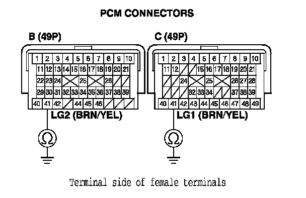
10. Connect PCM connectors B (49P) and C (49P).
11. Disconnect the output shaft (countershaft) speed sensor connector.
12. Turn the ignition switch to ON (II).
13. Measure the voltage between output shaft (countershaft) speed sensor connector terminal No. 1 and body ground.
Is there about 5 V?
YES - Go to step 17.
NO - Go to step 14.
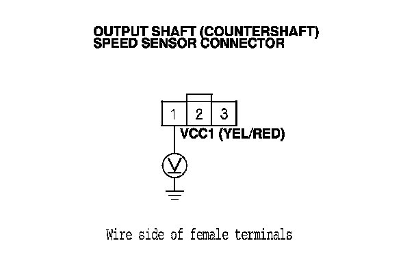
14. Turn the ignition switch to LOCK (0).
15. Disconnect PCM connector B (49P).
16. Check for continuity between PCM connector terminal B36 and output shaft (countershaft) speed sensor connector terminal No. 1.
Is there continuity?
YES - Go to step 32.
NO - Repair open in the wire between PCM connector terminal B36 and the output shaft (countershaft) speed sensor, then go to step 37.
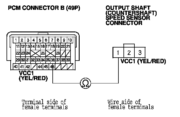
17. Turn the ignition switch to LOCK (0).
18. Disconnect PCM connector B (49P).
19. Check for continuity between output shaft (countershaft) speed sensor connector terminal No. 2 and body ground.
Is there continuity?
YES - Repair short in the wire between PCM connector terminal B38 and the output shaft (countershaft) speed sensor connector, then go to step 37.
NO - Go to step 20.
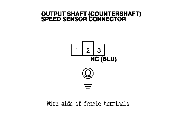
20. Disconnect PCM connector C (49P).
21. Check for continuity between PCM connector terminal C15 and output shaft (countershaft) speed sensor connector terminal No. 3.
Is there continuity?
YES - Go to step 22.
NO - Repair open in the wire between the output shaft (countershaft) speed sensor connector and PCM connector terminal C15, then go to step 37.
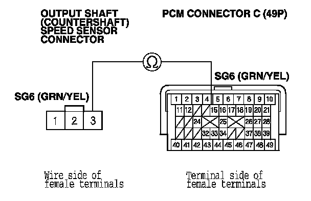
22. Connect PCM connectors B (49P) and C (49P).
23. Turn the ignition switch to ON (II).
24. Measure the voltage between output shaft (countershaft) speed sensor connector terminals No. 2 and No. 3.
Is there about 5 V?
YES - Go to step 28.
NO - Go to step 25.
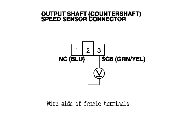
25. Turn the ignition switch to LOCK (0).
26. Disconnect PCM connector B (49P).
27. Check for continuity between PCM connector terminal B38 and output shaft (countershaft) speed sensor connector terminal No. 2.
Is there continuity?
YES - Go to step 32.
NO - Repair open in the wire between PCM connector terminal B38 and the output shaft (countershaft) speed sensor, then go to step 37.
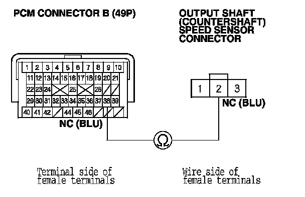
28. Connect the output shaft (countershaft) speed sensor connector.
29. Clear the DTC with the HDS.
30. Start the engine. Run the vehicle in D with the engine speed at 2,000 rpm or higher, for at least 10 seconds.
31. Monitor the OBD STATUS for P0721 or P0722 in the DTCs/Freeze Data in A/T Mode Menu for a pass/fail.
Does the HDS indicate FAILED?
YES - Replace the output shaft (countershaft) speed sensor, A/T Output Shaft (Countershaft) Speed Sensor Replacement then go to step 37.
NO - Go to step 32.
32. Reconnect all connectors.
33. Update the A/T software in the PCM if it does not have the latest software, Service and Repair or substitute a known-good PCM. How to Troubleshoot A/T Systems
34. Start the engine, run the vehicle in D, and hold the vehicle at speeds over 12 mph (20 km/h) for at least 10 seconds when the transmission is not shifting.
35. Check for Temporary DTCs or DTCs with the HDS.
Is DTC P0721 or P0722 indicated?
YES - If the PCM was updated, substitute a known-good PCM, How to Troubleshoot A/T Systems then recheck. If the PCM was substituted, go to step 1.
NO - Go to step 36.
36. Monitor the OBD STATUS for P0721 or P0722 in the DTCs/Freeze Data in A/T Mode Menu for a pass/fail.
Does the HDS indicate PASSED?
YES - If the PCM was updated, troubleshooting is complete. If the PCM was substituted, replace the original PCM. Service and Repair If any other DTCs were indicated on step 35, go to the indicated DTC's troubleshooting.
NO - If the HDS indicates FAILED, check for poor connections and loose terminals at the output shaft (countershaft) speed sensor and the PCM. If the PCM was updated, substitute a known-good PCM, How to Troubleshoot A/T Systems then recheck. If the PCM was substituted, go to step 1. If the HDS indicates NOT COMPLETED, return to step 34 and recheck.
37. Clear the DTC with the HDS.
38. Start the engine. Run the vehicle in D with the engine speed at 2,000 rpm or higher, for at least 10 seconds.
39. Check for Temporary DTCs or DTCs with the HDS.
Is DTC P0721 or P0722 indicated?
YES - Check for poor connections and loose terminals at the output shaft (countershaft) speed sensor and the PCM, then go to step 1.
NO - Go to step 40.
40. Monitor the OBD STATUS for P0721 or P0722 in the DTCs/Freeze Data in A/T Mode Menu for a pass/fail.
Does the HDS indicate PASSED?
YES - Troubleshooting is complete. If any other DTCs were indicated on step 39, go to the indicated DTC's troubleshooting.
NO - If the HDS indicates FAILED, check for poor connections and loose terminals at the output shaft (countershaft) speed sensor and the PCM, then go to step 1. If the HDS indicates NOT COMPLETED, return to step 38 and recheck.