A2-1x
SRS DTC Troubleshooting: A2-1x (x can be 0 thru 9 or A thru F)
DTC A2-1x ("x" can be 0 thru 9 or A thru F):Faulty Power Supply (VB Line)
NOTE: Before doing this troubleshooting procedure, review SRS Precautions and Procedures, Service and Repair General Troubleshooting Information, Initial Inspection and Diagnostic Overview and Battery Terminal Disconnection and Reconnection. Procedures
1. Check the No. 22 (10 A) fuse in the under-dash fuse/relay box.
Is the fuse OK?
YES - Go to step 11.
NO - Go to step 2.
2. Replace the No. 22 (10 A) fuse.
3. Turn the ignition switch to ON (II) and wait for 30 seconds. Then turn the ignition switch to LOCK (0).
4. Check the No. 22 (10 A) fuse.
Is the fuse OK?
YES - The system is OK at this time.
NO - Go to step 5.
5. Replace the No. 22 (10 A) fuse.
6. Turn the ignition switch to LOCK (0). Disconnect the negative cable from the battery, then wait for 3 minutes.
7. Disconnect SRS unit connector A (28P) from the SRS unit. Service and Repair
8. Reconnect the negative cable to the battery.
9. Turn the ignition switch to ON (II), and wait for 30 seconds. Then turn the ignition switch to LOCK (0).
10. Check the No. 22 (10 A) fuse.
Is the fuse OK?
YES - Short to ground in the SRS unit; replace the SRS unit. SRS Unit Replacement
NO - Short to ground in the dashboard wire harness or in the under-dash fuse/relay box No. 22 (10 A) fuse line; replace the dashboard wire harness. If the problem is still there, replace the under-dash fuse/relay box. Under-Dash Fuse/Relay Box Removal and Installation
11. Turn the ignition switch to LOCK (0). Disconnect the negative cable from the battery, then wait for 3 minutes.
12. Disconnect SRS unit connector A (28P) from the SRS unit. Service and Repair
13. Reconnect the negative cable to the battery.
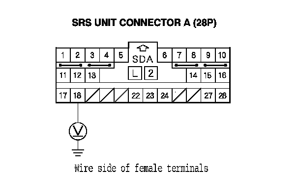
14. Measure the voltage between the terminal No. 18 of SRS unit connector A (28P) and body ground. Turn the ignition switch to ON (II), and measure the voltage. There should be battery voltage with the ignition on.
Is there battery voltage?
YES - Faulty SRS unit or poor connection at SRS unit connector A (28P) and the SRS unit; check the connection. If the connection is OK, replace the SRS unit. SRS Unit Replacement
NO - Go to step 15.
15. Turn the ignition switch to LOCK (0).
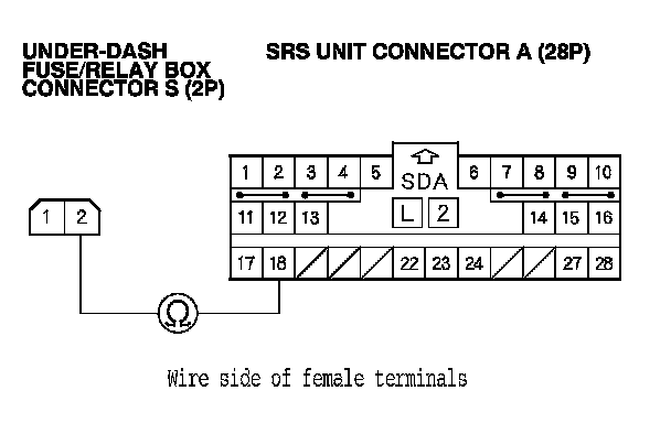
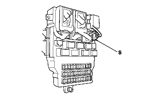
16. Disconnect under-dash fuse/relay box connector S (2P).
17. Measure the resistance between the terminal No. 1 of the under-dash fuse/relay box connector S (2P) and the terminal No. 18 of SRS unit connector A (28P). There should be less than 1.0 Ohms.
Is the resistance as specified?
YES - Open in the under-dash fuse/relay box or poor connection between connector S (2P) and the under-dash fuse/relay box; check the connection. If the connection is OK, replace the under-dash fuse/relay box. Under-Dash Fuse/Relay Box Removal and Installation
NO - Open in the dashboard wire harness; replace the dashboard wire harness.