B1840
DTC Troubleshooting: B1840
DTC B1840: Tilt Motor Pulse Error
NOTE: If you are troubleshooting multiple DTCs, be sure to follow the instructions in B-CAN System Diagnosis Test Mode A. Troubleshooting - B-CAN System Diagnosis Test Mode A
1. Clear the DTCs with the HDS.
2. Turn the ignition switch to LOCK (0) and then back ON (II).
3. Operate the tilt switch in each direction for more than 1 second.
4. Check for DTCs with the HDS.
Is DTC B1840 indicated?
YES - Go to step 5.
NO - Intermittent failure, the system is OK at this time. Check for loose or poor connections.
5. Clear the DTCs with the HDS.
Is DTC B1841 also indicated?
YES - Go to step 17.
NO - Go to step 6.
6. Clear the DTCs with the HDS.
7. Turn the ignition switch to LOCK (0) and then back ON (II).
8. Operate the tilt switch for 2 seconds, and check the tilt motor operation.
Does the tilt motor run smoothly?
YES - Go to step 9.
NO - Go to step 26.
9. Turn the ignition switch to LOCK (0).
10. Disconnect power tilt/telescopic control unit connector A (16P).
11. Disconnect the tilt motor/position sensor 8P connector.
12. Check for continuity between power tilt/telescopic control unit connector A (16P) terminals No. 4, No. 12, and No. 16 and tilt motor/position sensor 8P connector terminals No. 6, No. 7, and No. 8 respectively.
Is there continuity?
YES - Go to step 13.
NO - Repair open in the wire.
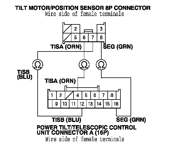
13. Check for continuity between body ground and power tilt/telescopic control unit connector A (16P) terminals No. 4 and No. 12 individually.
Is there continuity?
YES - Repair short to ground in the wire.
NO - Go to step 14.
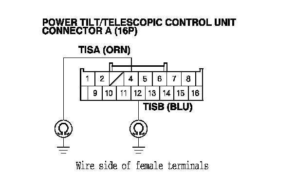
14. Reconnect power tilt/telescopic control unit connector A (16P).
15. Turn the ignition switch to ON (II).
16. Measure the voltage between tilt motor/position sensor 8P connector terminals No. 6 and No. 8 and between terminals No. 7 and No. 8.
Is there about 5 V?
YES - Faulty tilt motor/position sensor, replace the tilt motor assembly.
NO - If there is no voltage, replace the power tilt/telescopic control unit. If there is battery voltage, repair short in the wire.
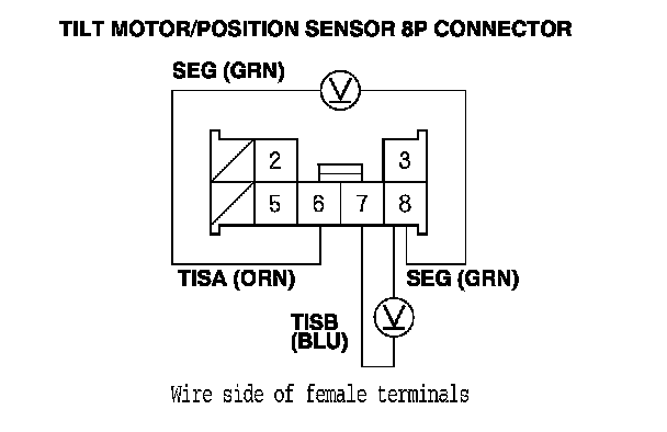
17. Turn the ignition switch to LOCK (0).
18. Disconnect power tilt/telescopic control unit connector A (16P).
19. Disconnect the tilt motor/position sensor 8P connector.
20. Check for continuity between power tilt/telescopic control unit connector A (16P) terminals No. 2 and No. 16 and tilt motor/position sensor 8P connector terminals No. 5 and No. 8 respectively.
Is there continuity?
YES - Go to step 21.
NO - Repair open in the wire.
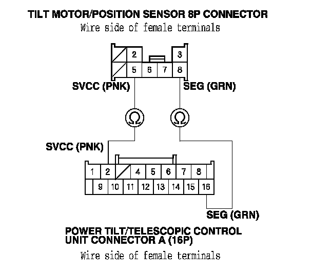
21. Disconnect the telescopic motor/position sensor 6P connector.
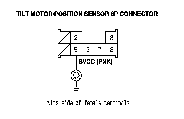
22. Check for continuity between tilt motor/position sensor 8P connector terminal No. 5 and body ground.
Is there continuity?
YES - Repair short to ground in the wire.
NO - Go to step 23.
23. Reconnect power tilt/telescopic control unit connector A (16P).
24. Turn the ignition switch to ON (II).
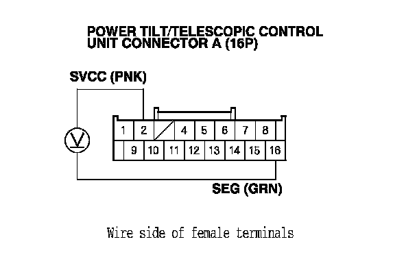
25. Measure the voltage between power tilt/telescopic control unit connector A (16P) terminals No. 2 and No. 16.
Is there battery voltage when the tilt switch is operated?
YES - Faulty tilt motor/position sensor, replace the tilt motor assembly.
NO - Replace the power tilt/telescopic control unit.
26. Turn the ignition switch to LOCK (0).
27. Disconnect power tilt/telescopic control unit connector B (8P).
28. Disconnect the tilt motor/position sensor 8P connector.
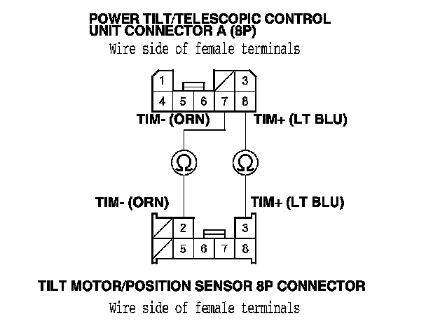
29. Check for continuity between power tilt/telescopic control unit connector B (8P) terminals No. 7 and No. 8 and tilt motor/position sensor 8P connector terminals No. 2 and No. 3 respectively.
Is there continuity?
YES - Go to step 30.
NO - Repair open in the wire.
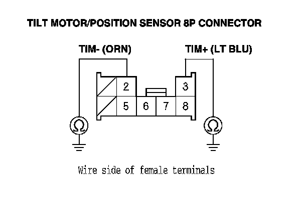
30. Check for continuity between body ground and tilt motor/position sensor 8P connector terminals No. 2 and No. 3 individually.
Is there continuity?
YES - Repair short to ground in the wire.
NO - Go to step 31.
31. Test the tilt motor. Testing and Inspection
Is the motor OK?
YES - Replace the power tilt/telescopic control unit.
NO - Replace the tilt motor/position sensor.