Part 1 of 2
System Diagnostic ModeStart-up procedure and Diagnostic Menu
There are two ways to enter the diagnostic mode:
1. Connect the SCS connector to the navigation service connector located in the trunk. Then turn the ignition switch to the ON (II). The display will go directly to the diagnostic menu screen shown below.
NOTE: When finished troubleshooting, make sure to remove the SCS connector.
2. Turn the ignition switch ON (II). Use the navigation display hard buttons as described below:
Make sure the battery is in good condition, then press and hold the three buttons (Menu, Map/Guide, and Cancel), and keep them pressed for approximately 5 seconds. The display screen will go directly to the Select Diagnosis Items menu shown below.
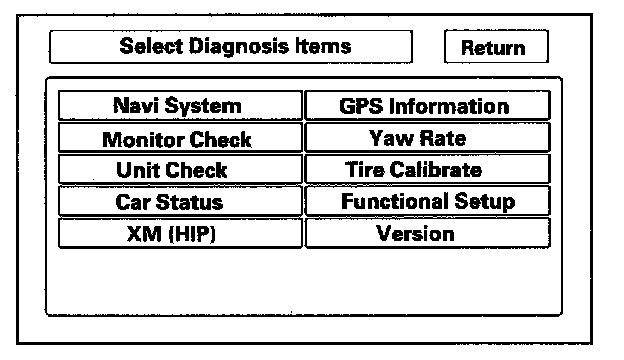
3. After the display changes to the Select Diagnosis Items menu, select the item you want to check and the diagnostic will start. To return to the previous screen, select Return.
- Navi System (Link)
- Monitor Check
- Unit Check
- Car Status
- XM (HIP)
- GPS Information
- Yaw Rate
- Tire Calibrate
- Functional Setup
- Version
Factory diagnostic screen "In Line Diag"
NOTE: If the vehicle left the factory in the factory diagnostic mode, you will see this screen every time you turn on the ignition.
When a navigation control unit is powered up for the first time at the factory or after replacement with a new or remanufactured navigation unit, the factory diagnosis screen (In Line Diag) shows up. Normally the factory done the steps necessary to verify proper operation and terminate the factory diagnostic. Until the proper confirmation sequence is done, the screen will show up every time the vehicle is started.
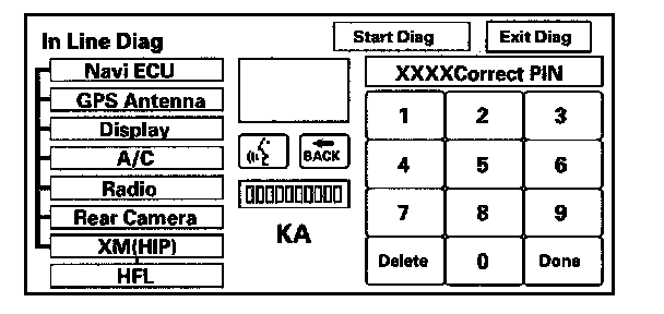
Follow the steps below to prevent the screen from showing up in the future:
- Press and hold the buttons (Menu + Map/Guide + Cancel) for about 5 seconds (the Select Diagnosis items screen appears).
- Press and hold the Map/Guide button for 5 - 10 seconds (A screen with a Complete button, appears).
- Select Complete, then Return, and then turn the key off for 5 seconds. Do not disconnect the battery during this period as the unit is saving the setting to the SRAM memory. The In Line Diag should not appear again.
- Restart the vehicle, and confirm normal operation by completing the TQI of the Navigation System Service Bulletin.
Navi System Link
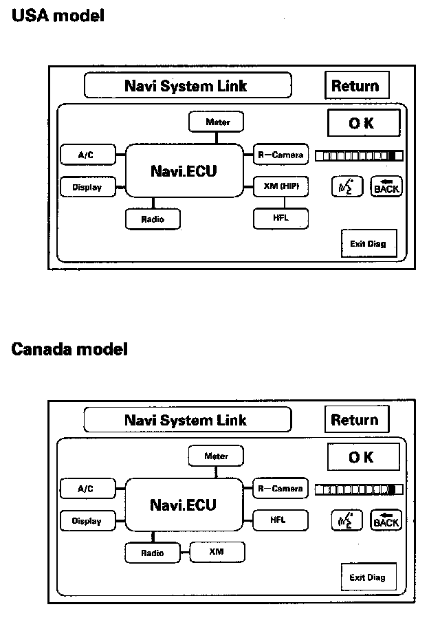
- This diagnostic tests the cables connecting the navigation components. Ensure that the ignition switch is in the ON (II) position. When the diagnostic begins, you hear a bong sound. The system is in a Detecting mode, and is waiting for all items in white to be tested. This includes the navigation voice control (TALK/BACK) buttons, and microphone. Press the navigation TALK button on the steering wheel, and in a normal voice, say testing. The TALK indicator on the screen should turn green, and the voice level indicator should move to at least the 6th bar to pass. Next, press the navigation BACK button. The Back indicator should turn green.
- If all of the communication lines connecting the system components, and the navigation TALK/BACK buttons/microphone check out OK (all block diagram items green), then the OK indicator turns green.
- If there is a problem with the system, the faulty system component item turns red, and the screen will show NG in red. Use the troubleshooting index, and other diagnostic screens to help locate the problem.
- The indication on the screen may not change until you cycle the ignition switch. After repairing the affected cable or system, repeat this diagnostic.
NOTE:
- Green boxes and a green OK indicate that the communications lines (cables) are intact. This diagnostic does not necessarily imply that the individual components are functioning properly. For instance, the GPS antenna wire may be crushed, but still show as green. A road test, or other diagnostic may be necessary to find the problem.
- A green box and link to the AcuraLink control unit (XM receiver) does not mean that the unit is receiving traffic information. Always verify that the client's account status is active, and compare to a known-good vehicle to ensure that there isn't local coverage problem.
- Select Return to return to the Diagnosis Menu.
NOTE:
- The mic level indicator must reach the 6th bar or greater to pass the test.
- If the XM link is red or flashing red, go to audio system symptom troubleshooting, or see XM (HIP) diagnostic screen. Audio System
Monitor Check
Overview of display unit
- The illumination cancel signal is provided by the gauge via B-CAN to the HVAC unit, then to the navigation unit via the U-ART bus.
- The display unit communicates with the navigation unit over its own GA-Net bus. Information sent by the navigation unit to the display unit includes commands to control the LCD back light.
- The security system protects the navigation display unit by daisy-chaining the security signal through it, and then passing the signal to the audio unit.
- The illumination input from the gauge brightness control provides back lighting for the buttons surrounding the screen.
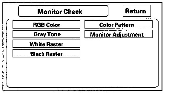
These screens allow you to troubleshoot the display unit. Select the item you want to troubleshoot, and follow the diagnostic instructions.
- RGB color
- Gray Tone
- White Raster
- Black Raster
- Color Pattern
- Monitor Adjustment
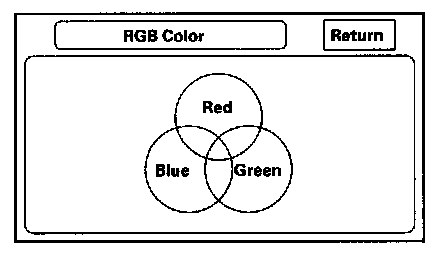
RGB Color
This screen verifies that the display unit is receiving the video (R, G, B and Composite sync) signals properly. The three primary colors should all be shown without distortion. The combination of all three should produce a central white section. If any of the colors are missing, troubleshoot for the color signal. If the picture has lines in it or scrolls horizontally, or vertically, troubleshoot for a Composite sync problem.
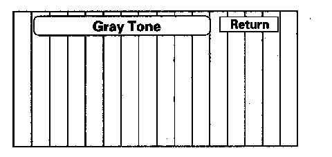
Gray Tone
This screen diagnoses problems with contrast. You should be able to see the changes from bar to bar across the scale. It is normal for the two bars on either side to appear the same.
White Raster
This diagnostic screen checks for pixels that may be dead (off). The entire display must be white. If there are dead pixels, replace the navigation unit.
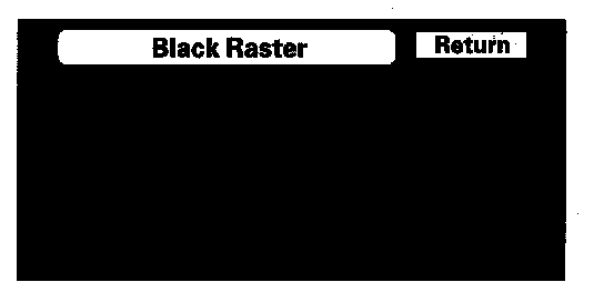
Black Raster
This diagnostic screen checks for pixels that may be stuck on. The entire display must be black. If pixels are stuck on, replace the navigation unit.
Color Pattern
The chart below shows the colors being used for the map and menu screens. This is for factory use only. To check the color signal use the RGB Color diagnostic found under the Monitor Check.
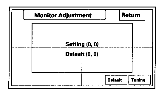
Monitor Adjustment
This allows you to center the navigation display. Use the joystick to move the picture up/down or left/right. It is unlikely that you will ever need to adjust the monitor position. The Default button will reset the display position to factory specifications.
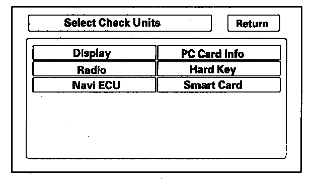
Unit Check
To start the test, select the item you want to check starts.
- Display
- Radio
- Navi ECU
- PC Card Info
- Hard Key
- Smart Card
Display
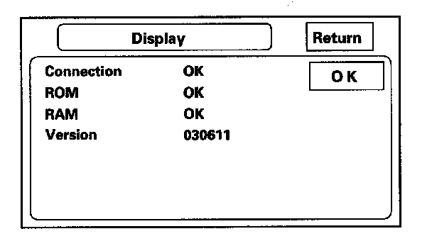
This diagnostic does additional checks on the communication bus between the control unit and the display. In addition, the internal electronics functionality are confirmed.
- When the connection is NG, first check for loose terminals at the navigation unit and the display unit connections. Next check for an open or short in the communication line between the navigation unit and the display unit. If you find the line has an open or short, replace the affected shielded harness.
- If the ROM or RAM is NG, replace the display unit.
- The version represents the software version in the display.
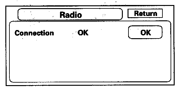
Radio
If the NG is indicated, check for loose audio unit connector.
NOTE: If the XM link was displayed red, but the radio link was displayed green in the navigation system link, refer to audio system symptom troubleshooting. Audio System
Navi ECU
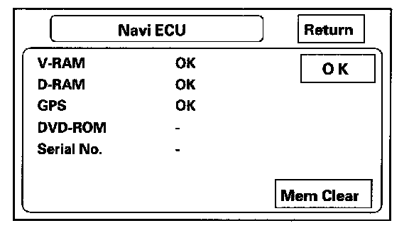
This screen looks for problems with the navigation unit. When you initiate this diagnosis, the navigation unit may delay up to a minute while the diagnosis runs.
NOTE: Do not try to end this diagnostic by pressing OK or Mem clear before it finishes, otherwise the system may reboot.
- If V-RAM or D-RAM is NG, then replace the navigation unit.
- If GPS indicates NG (ANT), then check the entire GPS antenna wire from the navigation unit to the antenna. If the wire is crushed or damaged, try a known good antenna. If this diagnostic reads OK, then order a new GPS antenna. If the diagnostic still reads NG (ANT), then replace the navigation unit.
- DVD ROM represents the database version on the DVD. You can find this information in either the Setup Screen Version, or in the Diagnostic Screen Version.
- Serial No. should be the same as the serial number found on the underside of the navigation unit. You need this number to obtain the security code from the Interactive Network (iN) system.
- The Mem Clr is for factory use and should not be used unless instructed by the factory.
Selecting this will clear the client's settings, personal information, GPS orbital data, and anything else stored in memory.
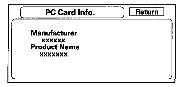
PC Card info.
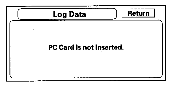
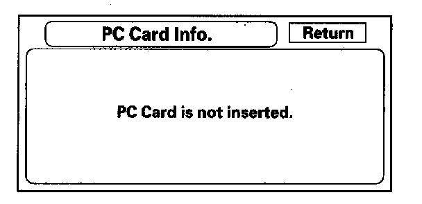
There is no PC Card in the PC slot, and the screen should say, PC Card is not inserted.
NOTE: Do not insert any card or object into the slot.
If the factory provides a PC card and instructs you to insert a card, then the screen displays the Manufacturer, and Product Name as shown in the following screen.
Hard Key
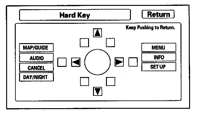
This diagnostic tests the interface dial, and the buttons that surround it. For this model, the interface dial and buttons do not use the GA-Net bus for communications.
To complete the test, touch each button on the vehicle's control panel, and move the interface dial to each indicated position. As each function is tested, the corresponding button on the display should highlight. To exit, push in and hold the selector knob.
NOTE: You cannot use the on screen return button to exit this function.
Smart Card
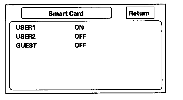
If the smart card is being used, you can check the card condition.
Car Status
Use this screen to confirm that the navigation unit is properly receiving input signals. Signals equal to (0) are OFF, and signals equal to (1) are ON. If the value on the display does not match the actual vehicle status, then check the wire carrying the signal.
- VSP-Vehicle Speed Pulse from PCM (Pin 6 of C-connector)
a. OFF (0) when vehicle is not moving
b. ON (1) when vehicle is moving
The VSP comes from the PCM as a dedicated signal. Internally, the navigation unit compares the actual VP on the map against street data to adjust the pulse to speed scaling factor. As this scaling factor becomes more accurate, the Level gradually increases from 0 to 10 (see the Tire Calibrate diagnostic screen).
- BACK-Reverse indication from taillight relay (Pin 5 of C-connector)
a. OFF (0) when the shift lever is in any position other than reverse
b. ON (1) when the shift lever is in reverse
The Back signal is used by the navigation unit to allow the map screen to show the VP moving backwards when in reverse. This signal is needed because the Speed Pulse has no direction indication.
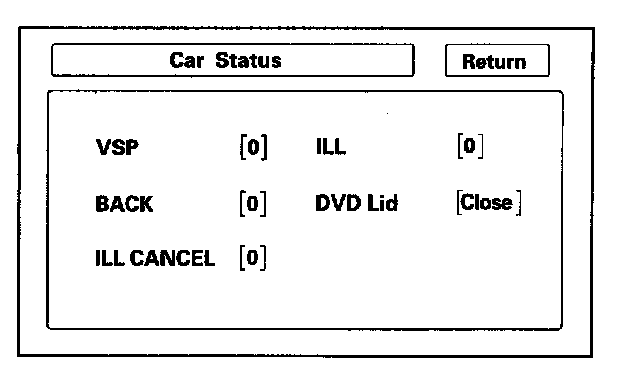
- ILL CANCEL
This function is not applied to this model.
- ILL-Illumination Indication (Pin 5 of navigation unit A-connector)
a. OFF (0) when parking lights, or headlights are off
b. ON (1) when parking lights, or headlights are on
The navigation uses the signal to determine whether to put the navigation screen into the Day or Night brightness mode. (Setup screen 1)
- DVD Lid-senses if the DVD door is open
a. (Close) when the door is closed
b. (Open) when the door is open
The navigation unit has a micro switch to detect this. If open is indicated when the door is closed, replace the navigation unit.
GPS Information
This screen shows the current status of GPS reception. The circular diagram shows the current location of the GPS satellites (yellow numbers) as they would appear in the sky. The outer circle represents the horizon (0 degrees elevation). The middle and inner circles represents 30 and 60 degrees respectively. The very center of the diagram (90 degrees elevation) is directly overhead. Nearby obstructions, like tall buildings will block satellites in that direction. That is why it is necessary to be in an open area to effectively troubleshoot GPS reception issues. The satellite numbers shown on the diagram correspond to the PRN number in the GPS Details screen. There are always at least 24 active GPS satellites in orbit. Because satellites fail, and have to be removed from service, spares are always parked in orbit, ready to be activated. This is why the PRN (satellite ID number) can be greater than 24.
NOTE: To use this screen for troubleshooting, the vehicle should be outside away from buildings, tall trees, and high-tension wires for at least 10 minutes with the engine running.
- The Number of Satellites box shows the number of acquired satellites (maximum of 12). It should contain four or more icons. If not troubleshoot for GPS icon is white or not shown.
- The Current Position shows latitude, longitude, and elevation (in feet). If there are less than four satellites, the elevation can be grossly inaccurate.
- The Date/Time field shows the current date, and also GMI time.
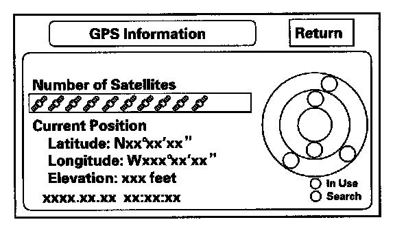
NOTE: Pressing the map guide button displays the satellite number on each circle.
GPS Detail
By pressing and holding the MENU button for 10 seconds, a GPS Detail screen appears. This screen displays real time incoming satellite positional data when the vehicle is outside in the open. The information shown on this screen is for factory use.
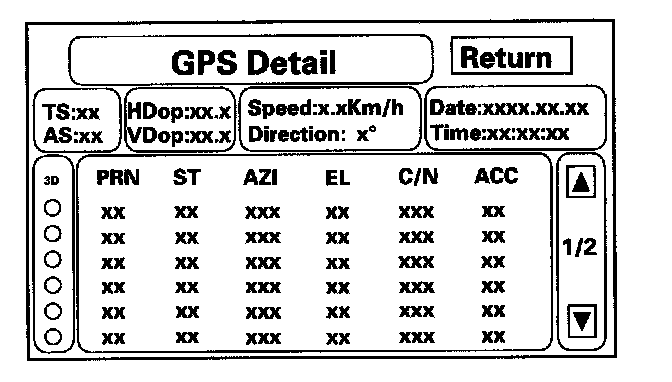
- The box TS/AS and H Dop/V Dop is for factory use.
- The Speed and Direction information is updated in real time when driving.
- The Date/Time Information is the same as in Setup screen 2 Adjust Time Zone/Clock.
- If the 3D icon is shown above the yellow dots, this implies that at least four satellites are available for map positioning, and the GPS indicator on the map screen will be green. See the Global Positioning System detailed explanation in the System Description.
- If the row of data in the table below begins with a yellow dot, the AZI and EL fields can be used to locate each satellite on the circular GPS diagram (see prior screen).
NOTE: The data shown in the GPS Detail screen is an example only.
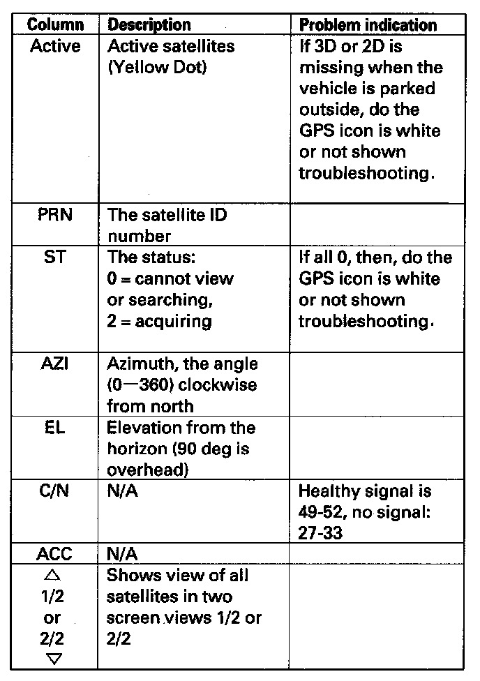
The table of values shown on the screen below has the following columns:
Yaw Rate
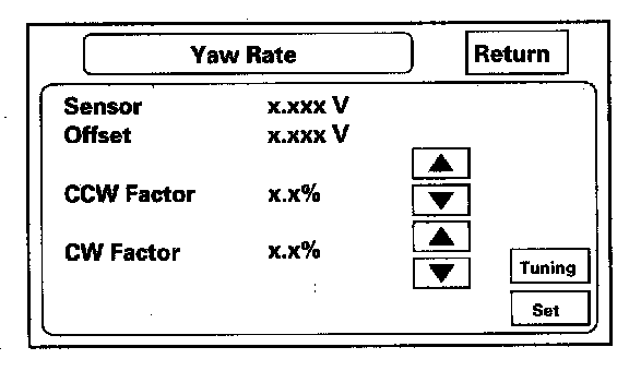
This diagnostic checks the yaw rate sensor in the control unit. This device detects when the vehicle turns, and repositions the vehicle position icon on the map screen. For more detailed information, see the yaw rate sensor theory of operation under System Description.
- Sensor indicates the voltage output from the yaw rate sensor. It should indicate about 2.500 volts when stopped.
- Offset is the reference voltage or standard within the yaw rate sensor. It also should indicate about 2.500 volts when stopped.
- A sensor output voltage LOWER than the Offset voltage indicates that the vehicle is turning to the right.
- A sensor output voltage HIGHER than the Offset voltage indicates that the vehicle is turning to the left.
- The yaw rate offset, and sensor should both indicate about 2.500 volts when stopped. If either reads zero, or 5.000 volts, replace the navigation unit.
- The yaw rate offset and sensor should be within ± 0.01 V of each other when stopped. The sensor value should change relative to the offset as the car is turned while driving. If not, replace the navigation unit.
Example: Car stopped
Normal
Offset 2.526 V
Sensor 2.516 - 2.536 V
Abnormal
Offset 2.526 V
Sensor 2.623 V
Example: Car turning
Normal
Offset 2.526 V
Sensor 2.678 V (left turn) 2.478 V (right turn)
Abnormal
Offset 2.526 V
Sensor 2.623 V (no change on turns)
- Sensitivity study represents the status of the internal tuning function. At initialization, this value starts at 6 and increases to #10 as the internal correction values become more accurate.
- The settings CCW Cal Factor, CW Cal Factor, and Set are for factory use only. THIS SHOULD NEVER BE ADJUSTED.
- For detailed analysis of the yaw rate select tuning.
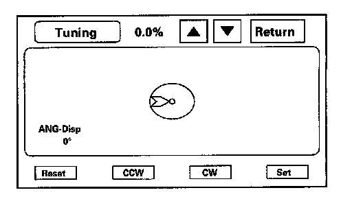
Yaw Rate Tuning
This diagnostic allows you to graphically display problems with the yaw rate sensor.
- The ANG-Disp value accumulates any differences between the offset, and sensor voltages (see Yaw Rate diagnostic). When the sensor is functioning normally, the random changes in these two voltages generally cancels out, so the value is 0. However if one voltage is consistently higher than the other, then the ANG-Disp value accumulates the constant change.
- The Reset button temporarily clears the angular accumulation (ANG-Disp), and clears the display dots.
- Do not touch the CCW, CW, or Set buttons. These are used for factory setup only.
Two tests are explained below. For gross problems with the sensor, the stationary test usually confirms whether the sensor is defective. For yaw rate issues related to driving, do the road test described below.
1. Stationary test: If the VP icon spins in place and the ANG-Disp value slowly increases or decreases, the yaw rate sensor is defective. Replace the navigation control unit.
2. Road test: Drive the vehicle on a very straight road. Enter the diagnostic mode, select Yaw rate, and touch the Tuning button. While driving down a straight road, the white dots should trace a straight line across the screen. However, if you are driving on a straight road, and you notice the dots constantly dropping down or heading up as you drive, the navigation control unit's yaw sensor is defective. You can touch Reset to clear ANG-Disp, and dotted lines.
If either test above fails, please enter Yaw rate sensor defective for the problem description, on the Navigation core return form.
Tire Calibrate
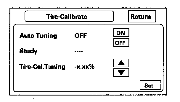
As the vehicle moves, the navigation system receives speed pulses from the PCM. These pulses are converted using a conversion factor to a mph speed that moves the vehicle position (VP) on the map. The navigation system has an internal tuning function that generates and refines this factor based on actual driving. The Study indicates the status of the tuning. At navigation initialization, it begins at 0, and increases to 10 as the navigation system is used.
- The Auto Tuning is factory set to ON, and should remain on.
- The Study indicates the tuning status. If it is less than 10, the unit is still calibrating.
- The Tire-Cal. Tuning and Set should not be used. It is for factory use only.
Functional Setup
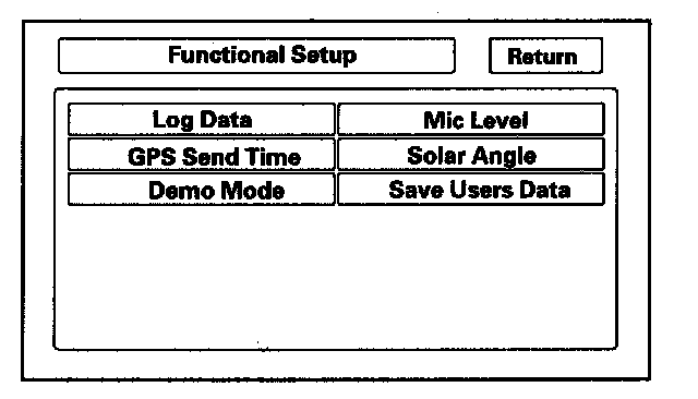
Select the item you want to check.
- Log Data
- GPS Send Time
- Demo Mode
- Mic Level
- Solar Angle
- Save Users Data
Solar Angle
This screen graphically displays the sun's position as determined by GPS. The HVAC system uses the navigation systems sun's angle, along with the sunlight sensor to control the driver/passenger A/C air flow. The heat that the climate control unit removes varies, depending on the angle of the sun entering the vehicle. This screen is for factory use only, and should not be adjusted.
- The screen shows a circular diagram of the sky oriented in the direction that the vehicle is pointing. During daylight hours a red dot is shown, representing the direction and elevation of the sun. The outer circle represents the horizon (0 degrees elevation). The middle circle is 30 degrees, the center circle is 60 degrees, and the very center is directly overhead (90 degrees).
- The manual tuning button should always be OFF.
- The Angle is the angle that the sun (shown with red dot) is above the horizon.
- The vehicle value represents the angle, clockwise from North, to the direction that the vehicle position (VP) icon is pointing (always points straight up).
- The direction value is the angle, measured clockwise from the VP (straight up) to the suns position.
- The reliability ranges from 1 to 3, and represents the accuracy of the Vehicle Position relative to the sun.