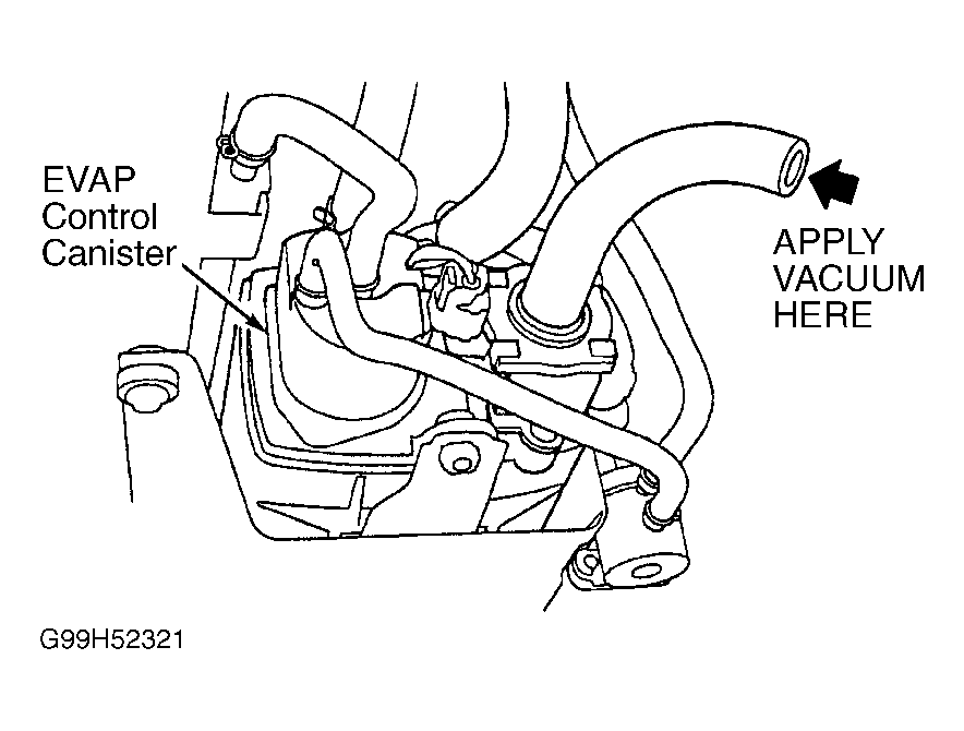
- Disconnect vacuum hose from EVAP Canister Purge Valve (EVAP-CPV). Connect vacuum pump and hose to disconnected port on EVAP-CPV. Connect fused jumper wire between body ground and PCM 26-pin connector A terminal No. 23 (Red/Yellow wire). See Figure
and Figure
. Turn ignition switch ON (II). Apply vacuum to EVAP-CPV. If valve holds vacuum, go to next step. If valve does not hold vacuum, EVAP-CPV is okay. Go to step 4
.
- Turn ignition switch off. Disconnect EVAP-CPV 2-pin connector. Check continuity between body ground and EVAP-CPV 2-pin connector terminal No. 1 (Red/Yellow wire). If continuity is present, go to next step. If continuity is not present, repair open in Red/Yellow wire between EVAP-CPV 2-pin connector terminal No. 1 and PCM 26-pin connector A terminal No. 23.
- Turn ignition switch ON (II). Measure voltage between body ground and EVAP By-Pass Solenoid Valve (EVAP-BPSV) 2-pin connector terminal No. 2 (Black/Yellow wire). If battery voltage is present, replace EVAP-CPV. If battery voltage is not present, repair open in Black/Yellow wire between EVAP-CPV 2-pin connector terminal No. 2 and No. 20 ECU (PCM) (20-amp) fuse in underdash fuse relay box.
- EVAP By-Pass Solenoid Valve Test:
Disconnect vacuum hose from EVAP 2-way valve and connect vacuum pump and hose to exposed port. See Figure
. Turn ignition switch ON (II). Apply vacuum to EVAP 2-way valve. If valve does not hold vacuum, go to next step. If valve holds vacuum, EVAP-BPSV and EVAP 2-way valve are okay. Go to step 7
.
- Turn ignition switch off. Disconnect EVAP-BPSV 2-pin connector. Check continuity between body ground and EVAP-BPSV 2-pin connector terminal No. 2 (Pink/Black wire). If continuity is present, go to next step. If continuity is not present, replace EVAP-BPSV and "O" rings.
- Disconnect PCM 8-pin connector F. See Figure
and Figure
. Check continuity between body ground and EVAP-BPSV 2-pin connector terminal No. 2 (Pink/Black wire). If continuity is present, repair short in Pink/Black wire between PCM 8-pin connector F terminal No. 1 and EVAP-BPSV 2-pin connector terminal No. 2. If continuity is not present, substitute a known-good PCM, and recheck. If symptom or indication goes away, replace original PCM.
- EVAP Canister Vent Shut Valve Test:
Disconnect vacuum hose at EVAP Canister Vent Shut Valve (EVAP-CVSV). Connect vacuum pump to disconnected hose. See Fig 1
. Connect fused jumper wire between body ground and PCM 8-pin connector F terminal No. 5 (Red/White wire). Turn ignition switch ON (II). Apply vacuum to EVAP-CVSV port. If valve does not hold vacuum, go to next step. If valve holds vacuum, EVAP-CVSV is okay. Go to step 10
.
 Courtesy of AMERICAN HONDA MOTOR CO., INC.
- Turn ignition switch off. Disconnect EVAP-CVSV 2-pin connector. Check continuity between body ground and EVAP-CVSV 2-pin connector terminal No. 2 (Red/White wire). If continuity is present, go to next step. If continuity is not present, repair open in Red/White wire between EVAP-CVSV 2-pin connector terminal No. 2 and PCM 8-pin connector F terminal No. 5.
- Turn ignition switch ON (II). Measure voltage between body ground and EVAP-CVSV 2-pin connector terminal No. 1 (Black/Yellow wire). If battery voltage is present, replace EVAP-CVSV and "O" ring. If battery voltage is not present, repair open in Black/Yellow wire between EVAP-CVSV 2-pin connector terminal No. 1 and No. 20 ECU (PCM) (20-amp) fuse in underdash fuse relay box.
- Canister System Leak Test:
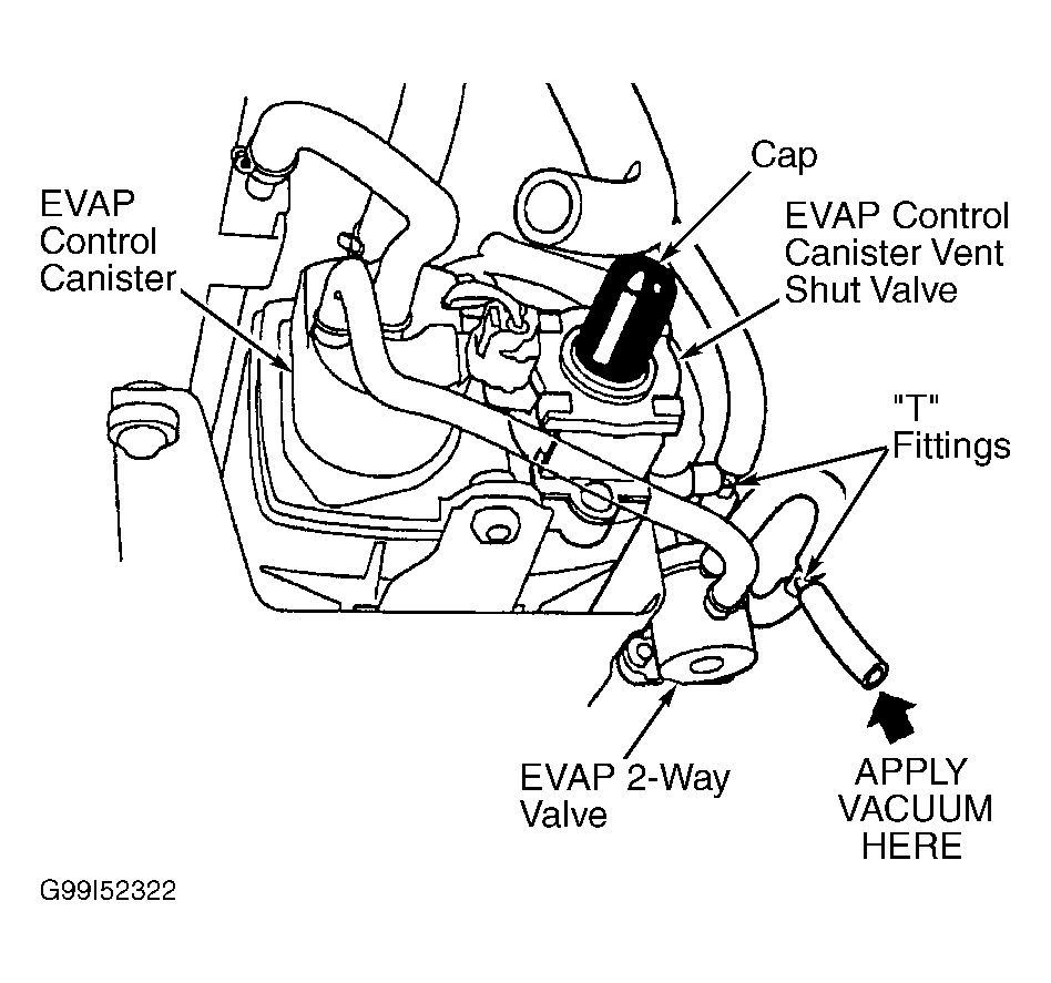
Turn ignition switch off. Connect 2 "T" fittings into hose between EVAP canister and EVAP 2-way valve. See Fig 2
. Connect Fuel Tank Pressure (FTP) sensor to one "T" fitting and vacuum pump to other "T" fitting. Remove vent hose from EVAP-CVSV and cap port to seal fresh air vent for EVAP canister. Turn ignition switch ON (II). While monitoring voltage with scan tool or measuring voltage between PCM 22-pin connector D terminals No. 15 (Green/Yellow wire) and No. 22 (Green/Black wire), slowly pump vacuum pump one stroke every 1-2 seconds. Pump vacuum until voltage drops to about 1.5 volts. Monitor voltage for about 20 seconds. If voltage does not drop to 1.5 volts and hold for at least 20 seconds, go to next step. If voltage drops to 1.5 volts and holds for at least 20 seconds, check EVAP-CVSV line and connections. Repair as necessary.
NOTE:
Ensure coolant temperature is greater than 95°F (35°C) and vacuum pump does not leak.
 Courtesy of AMERICAN HONDA MOTOR CO., INC.
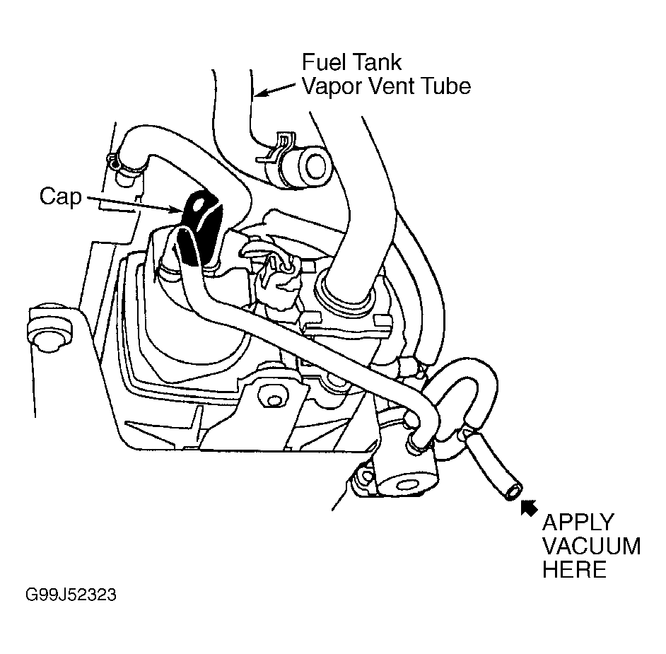
- Turn ignition switch off. Disconnect fuel tank vapor vent tube from EVAP canister and plug port. See Fig 3
. Turn ignition switch ON (II). While monitoring voltage with scan tool or measuring voltage between PCM 22-pin connector D terminals No. 15 (Green/Yellow wire) and No. 22 (Green/Black wire), slowly pump vacuum pump one stroke every 1-2 seconds. Continue to pump vacuum until voltage drops to about 1.5 volts. Monitor voltage for 20 seconds. If voltage does not drop to 1.5 volts and hold for 20 seconds, go to next step. If voltage drops to 1.5 volts and holds for 20 seconds, check fuel tank vapor vent line and connections.
NOTE:
Ensure coolant temperature is greater than 95°F (35°C) and vacuum pump does not leak.
 Courtesy of AMERICAN HONDA MOTOR CO., INC.
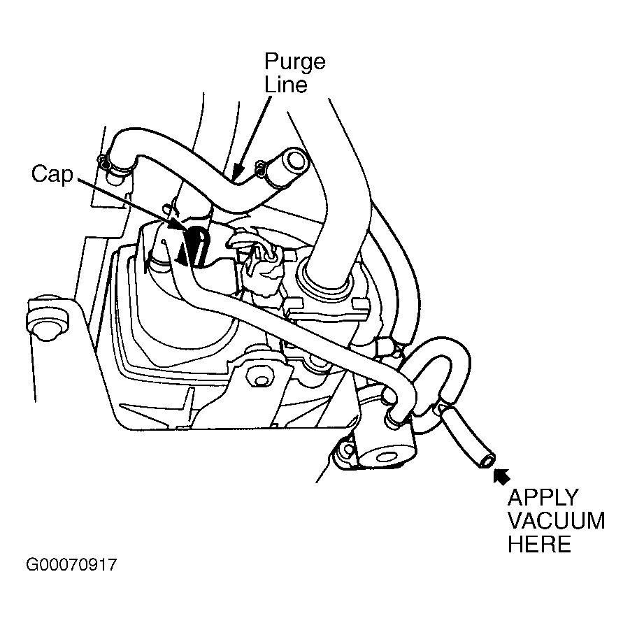
- Turn ignition switch off. Disconnect purge line hose from EVAP canister and plug port. See Fig 4
. Turn ignition switch ON (II). While monitoring voltage with scan tool or measuring voltage between PCM 22-pin connector D terminals No. 15 (Green/Yellow wire) and No. 22 (Green/Black wire), slowly pump vacuum pump one stroke every 1-2 seconds. Continue to pump vacuum until voltage drops to about 1.5 volts. Monitor voltage for 20 seconds. If voltage does not drop to 1.5 volts and hold for 20 seconds, replace EVAP canister. If voltage drops to 1.5 volts and holds for 20 seconds, check EVAP canister purge valve line and connections. If they are okay, check EVAP 2-way valve. See EVAP 2-Way Valve Test
.
NOTE:
Ensure coolant temperature is greater than 95°F (35°C) and vacuum pump does not leak.
 Courtesy of AMERICAN HONDA MOTOR CO., INC.