Removal & Installation (3.2TL)
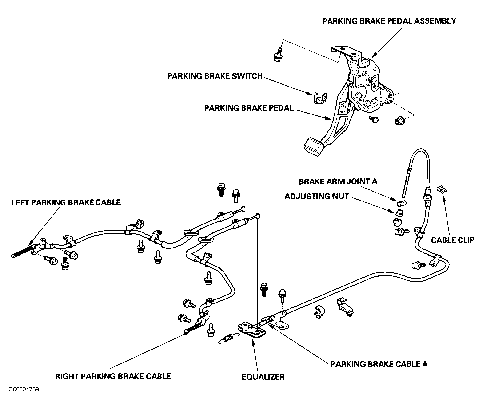
- Refer to exploded view as needed during this procedure. See Fig 1
.
- Raise and support rear of vehicle. Remove rear wheels.
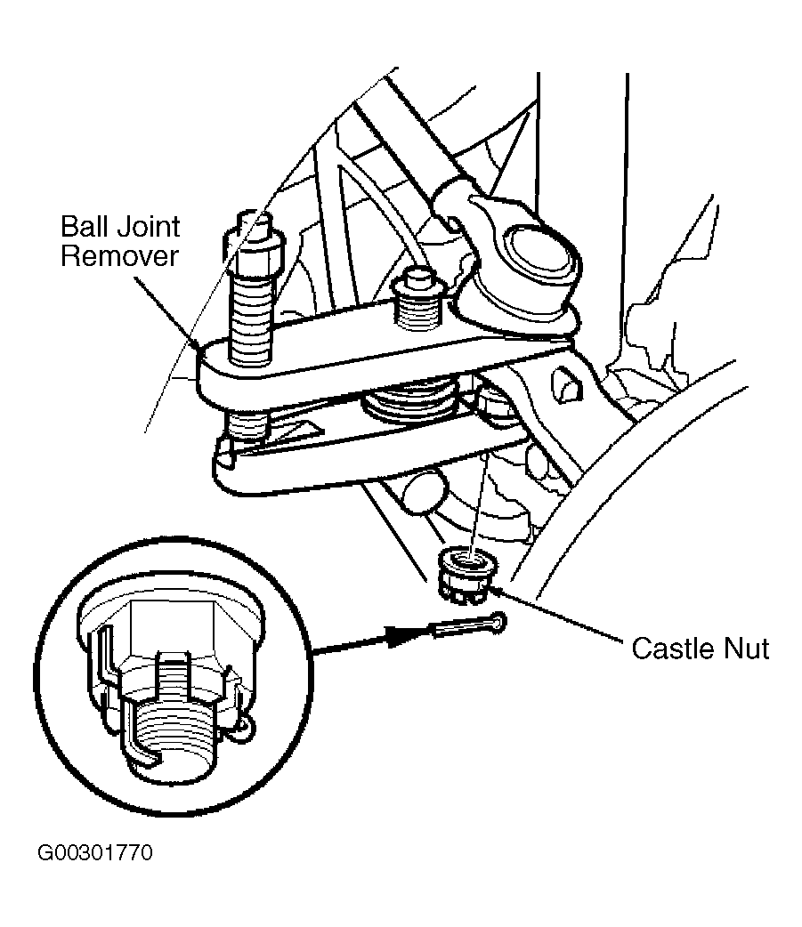
- Remove the cotter pin from the upper ball joint castle nut, and remove the nut. See Fig 2
. Using Ball Joint Remover (07MAC-SL00200), separate upper ball joint from knuckle.
- Remove rear brake rotors. See DISC BRAKE ROTOR
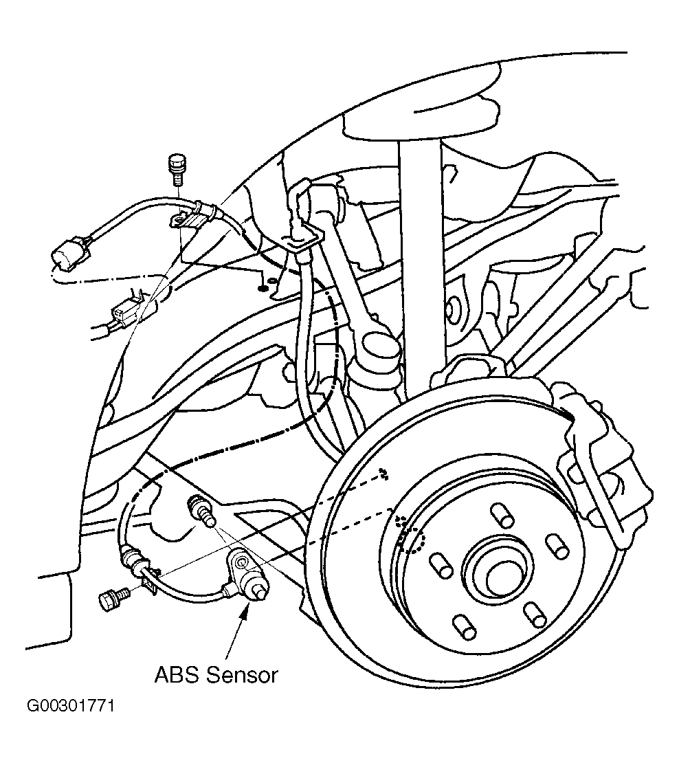
. Remove the ABS sensor from the brake backing plate. See Fig 3
.
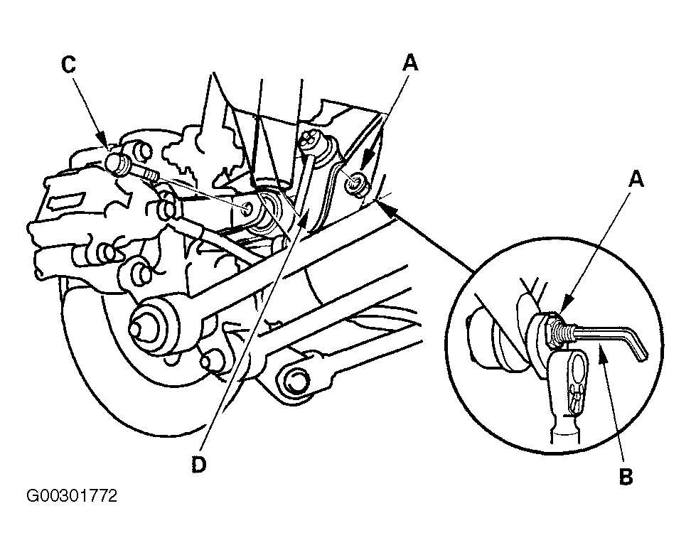
- Remove the flange nut "A" from the stabilizer link while holding the stabilizer link stud with a hex wrench "B". See Fig 4
. Remove the damper lower mounting bolt "C", and the stabilizer link mounting bracket "D".
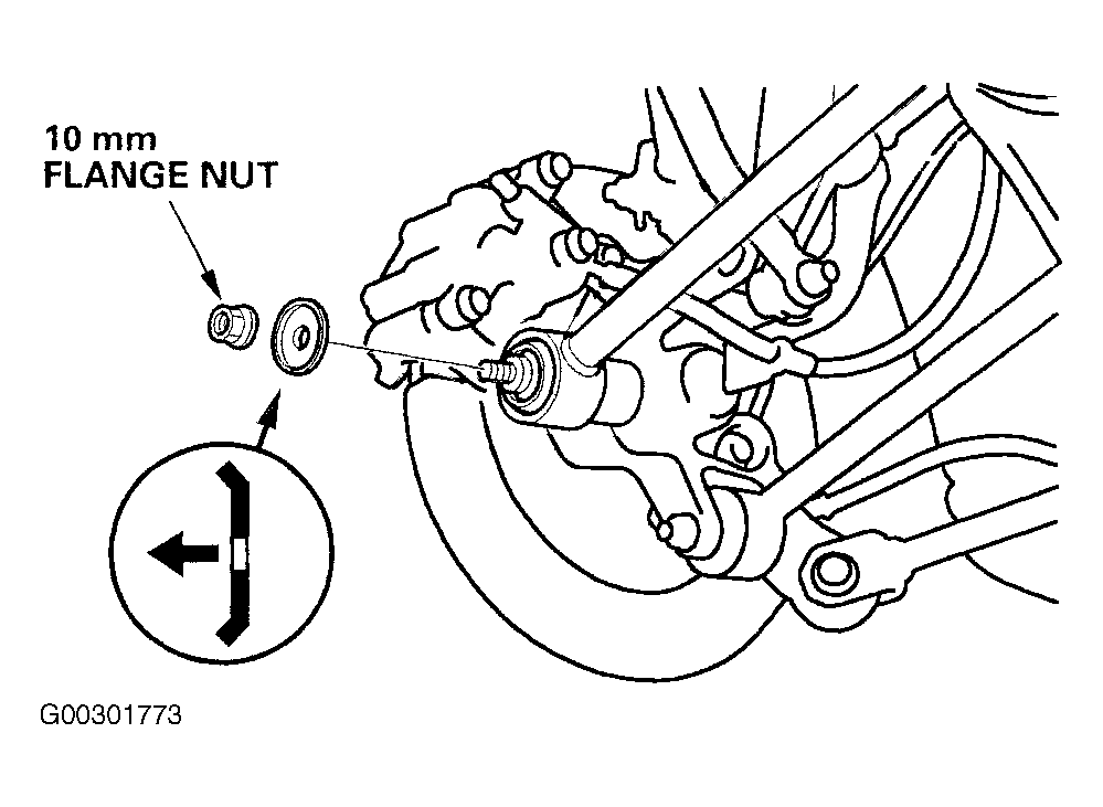
- Remove 10 mm control arm flange nut from the rear knuckle. See Fig 5
.
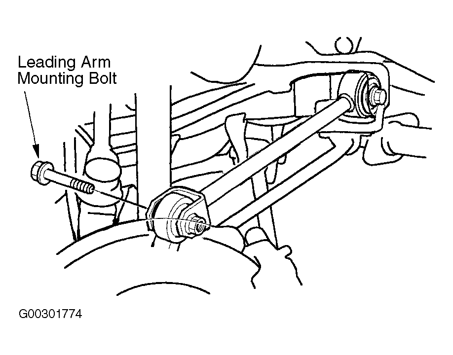
- Remove the leading arm mounting bolt from the rear knuckle. See Fig 6
.
- Remove the backing plate flange nuts. See Figure
.
- Remove rear disc brake rotor and hub. See DISC BRAKE ROTOR
.
- Remove parking brake shoes. See PARKING BRAKE SHOES
.
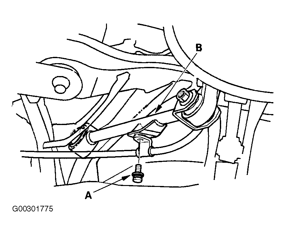
- Remove backing plate from rear knuckle. Remove parking brake cable mounting bolt "A" from trailing arm "B". See Fig 7
.
- Remove the parking brake cable mounting bolts from the backing plate "A", and remove the cable "B". See Figure
.
- To install, reverse removal procedure. Tighten components to specification. See TORQUE SPECIFICATIONS
. Use NEW cotter pin. Before installing the wheel, clean the mating surfaces on the brake disc and inside of the wheel. Adjust the parking brake. See PARKING BRAKE
under adjustments. Check rear wheel alignment, and adjust it if necessary.
 Courtesy of AMERICAN HONDA MOTOR CO., INC.
 Courtesy of AMERICAN HONDA MOTOR CO., INC.
 Courtesy of AMERICAN HONDA MOTOR CO., INC.
 Courtesy of AMERICAN HONDA MOTOR CO., INC.
 Courtesy of AMERICAN HONDA MOTOR CO., INC.
 Courtesy of AMERICAN HONDA MOTOR CO., INC.
 Courtesy of AMERICAN HONDA MOTOR CO., INC.