"D5" Indicator Light Does Not Illuminate
- Turn ignition switch to ON position. Move shifter to "D5" position. If "D5" indicator light does not illuminate, go next step. If "D5" indicator light illuminates, check for loose Powertrain Control Module (PCM) connectors. Repair as necessary.
- Turn ignition switch to OFF position. Remove PCM. See POWERTRAIN CONTROL MODULE (PCM)
under REMOVAL & INSTALLATION. Disconnect PCM 25-pin connector "B". Check for continuity individually between ground and terminals B20 (Brown/Yellow wire) and B22 (Brown/Yellow wire) of PCM 25-pin harness connector "B". See Fig 1
. If continuity exists, go to next step. If continuity does not exist, repair open in Brown/Yellow wires between PCM 25-pin connector "B" and ground (located left side of engine, below intake hose, next to radiator hose). See WIRING DIAGRAMS
.
- Turn ignition switch to ON position. Check for voltage between ground and terminals B1 and B9 (Yellow/Black wires) of PCM 25-pin harness connector "B". If battery voltage exists, go to next step. If battery voltage does not exist, repair open or short in Yellow/Black wires between PCM 25-pin connector "B" and terminal No. 6 of PGM-FI main relay 7-pin harness connector (located behind left instrument panel lower cover, left of steering column, above brake switch).
- Check continuity between ground and terminals B20 and B22 (Brown/Yellow wires). If continuity exists, go to next step. If continuity does not exist, repair open in appropriate Brown/Yellow wire between PCM and ground (located next to upper radiator hose connection at engine).
- Turn ignition switch to OFF position. Reconnect PCM 25-pin connector "B". Connect positive voltmeter lead between terminal A28 (Green/Black wire) of instrument cluster 30-pin harness connector "A". Individually connect (backprobe) negative voltmeter lead to terminals B20 and B22 (Brown/Yellow wires) of PCM 25-pin harness connector "B". Turn ignition switch to ON position. Voltage should be present for 2 seconds. If voltage is present for 2 seconds, go to next step. If voltage is not present for 2 seconds, go to step 7
.
- Check for open in Green/Black wire between terminal A14 of PCM 32-pin connector "A" and terminal A28 of instrument cluster 30-pin connector "A". See WIRING DIAGRAMS
. If continuity does not exist, repair open in Green/Black wire between PCM and instrument cluster. If wire is okay, check for faulty "D5" indicator light bulb or faulty instrument cluster printed circuit board. Repair or replace as necessary.
- Check for loose PCM connectors. Repair as necessary. If connectors are okay, check A/T gear position switch. See A/T GEAR POSITION SWITCH
under COMPONENT TESTS. Replace as necessary. If switch is okay, substitute a known-good PCM and recheck. If problem is corrected, replace original PCM.
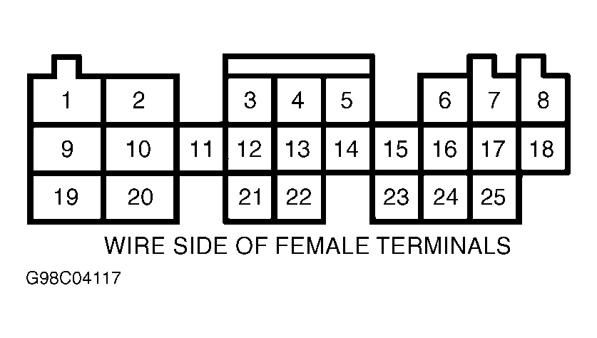 Courtesy of AMERICAN HONDA MOTOR CO., INC.