"D4" Indicator Light Does Not Illuminate: 3.5RL
- Turn ignition switch to ON position. "D4" indicator light should come on for about 2 seconds when ignition is first turned on. If indicator illuminates for 2 seconds, "D4" indicator is okay at this time. If "D4" indicator does not illuminate for 2 seconds, move shifter to "D4" position. If "D4" indicator light still does not illuminate, go to next step. If "D4" indicator light now illuminates, check for loose Powertrain Control Module (PCM) connectors. Repair as necessary. If connectors are okay, substitute a known-good PCM and recheck. See SUBSTITUTING PCM under SELF-DIAGNOSTIC SYSTEM in appropriate
SELF-DIAGNOSTICS - INTRODUCTION article. If problem goes away, replace original PCM.
- Turn ignition switch to OFF position. Remove PCM. See POWERTRAIN CONTROL MODULE (PCM) under REMOVAL & INSTALLATION. Disconnect PCM 26-pin connector "A" and PCM 16-pin connectors "B". Check for continuity between ground and PCM 26-pin harness connector "A" terminal No. 26 (Brown/Black wire) and PCM 16-pin harness connectors "B" terminal No. 9 (Brown/Black wire) individually. See Fig 1. If continuity exists, go to next step. If continuity does not exist, repair open in Brown/Black wires between PCM and ground connector G101. Ground connector G101 is located at top left side of engine, between engine coolant temperature (ECT) sensor housing and evaporative emission (EVAP) purge control solenoid valve. See WIRING DIAGRAMS .
- Turn ignition switch to ON position. Check voltage between PCM 26-pin harness connector "A" terminals No. 13 (Yellow/Black wire) and No. 26 (Brown/Black wire), and between PCM 16-pin connector "B" terminals No. 1 (Yellow/Black wire) and No. 9 (Brown/Black wire). If battery voltage is present, go to next step. If battery voltage is not present, repair open or short in Yellow/Black wire between fuse No. 6 (20-amp) located underdash fuse/relay box and PCM. See WIRING DIAGRAMS .
- Turn ignition switch to OFF position. Reconnect PCM 26-pin connector "A" and PCM 16-pin connectors "B". Backprobing, connect a DVOM between PCM 26-pin connector "A" terminal No. 26 (Brown/Black wire) and PCM 26-pin connector "E" terminal No. 23 (Brown/Black wire). See Fig 1. Turn ignition switch to ON position. Voltage should be present for 2 seconds. If voltage is present for 2 seconds, go to next step. If voltage is not present for 2 seconds, go to step 6.
- Check for open in Brown/Black wire between PCM 26-pin connector "E" and instrument cluster 30-pin connector "B" terminal No. 27. See WIRING DIAGRAMS . Repair as necessary. If wire is okay, check for faulty "D4" indicator light bulb or faulty instrument cluster printed circuit board. Repair or replace as necessary.
- Turn ignition switch to OFF position. Disconnect PCM 26-pin connector "E". Backprobing, check for continuity in Brown/Yellow wire between PCM 26-pin harness connector "E" terminal No. 23 and instrument cluster 30-pin connector "B" terminal No. 27. If continuity exists, go to next step. If continuity does not exist, repair open in Brown/Yellow wire between PCM 26-pin connector "E" and instrument cluster 30-pin connector "B".
- Check for continuity between ground and PCM 26-pin harness connector "E" terminal No. 23 (Brown/Yellow wire). If continuity exists, check for short in Brown/Yellow wire between PCM 26-pin connector "E" and instrument cluster 30-pin connector "B". If continuity does not exist, check for loose PCM connectors. Repair as necessary. If connectors are okay, check A/T gear position switch. See A/T GEAR POSITION SWITCH under COMPONENT TESTING. Replace as necessary. If switch is okay, substitute a known-good PCM and recheck. See SUBSTITUTING PCM under SELF-DIAGNOSTIC SYSTEM in appropriate
SELF-DIAGNOSTICS - INTRODUCTION article. If problem goes away, replace original PCM.
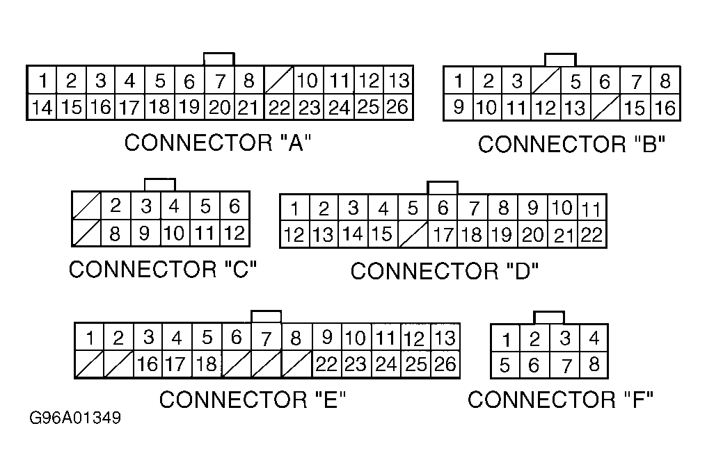 Courtesy of AMERICAN HONDA MOTOR CO., INC.