DTC P0335, P0336, P1336, P1337, P1381, P1382, P1386 Or P1387: CKP/CYP Sensors Malfunction
- Perform PCM reset procedure. See PCM RESET PROCEDURE/CLEARING CODES
under SELF-DIAGNOSTIC SYSTEM. Start engine. If DTC P0335, P0336, P1336, P1337, P1381, P1382, P1386 and/or P1387 resets, go to next step. If DTCs do not reset, problem is intermittent. System is okay at this time. Check for poor connections or loose wires between CKP/CYP sensor and PCM. Repair as necessary.
- Turn ignition off. Disconnect CKP/CYP sensor 8-pin connector. Measure CKP/CYP sensor resistance between specified sensor terminals. See CKP/CYP SENSOR TESTING
table. See Fig 1
. If resistance is 650-850 ohms, go to next step. If any resistance is not 650-850 ohms, replace CKP/CYP sensor assembly.
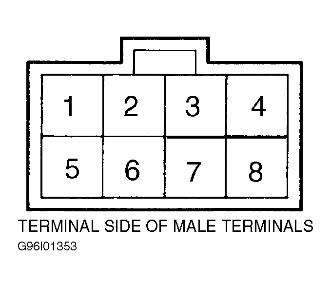 Courtesy of AMERICAN HONDA MOTOR CO., INC.
 CKP/CYP SENSOR TESTING
| Sensor Identification |
Terminals (Wire Color) |
| CKP-1 |
No. 1 (PNK) & No. 2 (GRY) |
| CKP-2 |
No. 3 (GRN/WHT) & No. 4 (BLK/WHT) |
| CYP-1 |
No. 7 (BLU/YEL) & No. 8 (YEL/GRN) |
| CYP-2 |
No. 5 (ORG) & No. 6 (WHT) |
- Check for continuity between ground and both terminals of suspect sensor. See CKP/CYP SENSOR TESTING
table. See Fig 1
. If continuity does not exist, go to next step. If continuity exists, replace CKP/CYP sensor.
- Reconnect CKP/CYP sensor 8-pin connector. Disconnect PCM 16-pin and 22-pin connectors. Measure resistance of suspect sensor between PCM connector terminals. See CKP/CYP SENSOR TERMINAL IDENTIFICATION
table. See
WIRING DIAGRAMS article. If resistance is 650-850 ohms, go to next step. If resistance is not 650-850 ohms, repair open in wire between suspect sensor and PCM.
- Using DVOM connected to ground, check for continuity at PCM 16-pin connector terminals No. 5, 6, 7, and 8. See CKP/CYP SENSOR TERMINAL IDENTIFICATION
table. If continuity exists, repair short to ground between suspect sensor and PCM. See
WIRING DIAGRAMS article. If continuity does not exist, substitute a known good PCM, then recheck. If symptom or indication goes away, replace original PCM.
CKP/CYP SENSOR TERMINAL IDENTIFICATION
| Sensor |
Sensor Terminal (Wire Color) |
PCM Terminal (Wire Color) |
| CKP-1 |
No. 1 (PNK) |
No. 8 (BLU) |
| CKP-1 |
No. 2 (GRY) |
No. 16 (WHT) |
| CKP-2 |
No. 3 (GRN/WHT) |
No. 15 (WHITE/RED) |
| CKP-2 |
No. 4 (BLK/WHT) |
No. 7 (BLU/RED) |
| CYP-1 |
No. 7 (BLU/YEL) |
No. 12 (BLK) |
| CYP-1 |
No. 8 (YEL/GRN) |
No. 6 (YEL) |
| CYP-2 |
No. 5 (ORG) |
No. 5 (YEL/RED) |
| CYP-2 |
No. 6 (WHT) |
No. 14 (BLK/RED) |