Instrument Cluster Dimmer Control Test: 3.2TL
- Turn ignition switch to OFF position. Remove dashboard lower cover. Disconnect dimmer control unit 6-pin connector. Check connector for open, loose or disconnected terminals. If terminals are bent, loose or corroded, repair as necessary and recheck system. If terminals are okay, go to next step.
- Using a DVOM, measure resistance between dimmer control unit terminal No. 4 (White/Red wire) and terminal No. 5 (Red/White wire). See Fig 1. While rotating dial, resistance should be 0-20,000 ohms. If resistance is as specified, go to next step. If resistance is not as specified, replace controller switch.
- Remove driver's multiplex control unit from driver's under-dash fuse/relay box. Check connector for open, loose or disconnected terminals. If terminals are bent, loose or corroded, repair as necessary and recheck system. If terminals are okay, go to next step.
- Using DVOM, check voltage between driver's under-dash fuse/relay box cavity A12 and ground. See Fig 2. If battery voltage exists, go to next step. If battery voltage does not exist, check fuse No. 13 (7.5-amp) located in passenger's under-dash fuse/rely box or open in White/Yellow wire between passenger's under-dash fuse/relay box. See WIRING DIAGRAMS . Repair as necessary.
- Check for continuity between driver's under-dash fuse/relay box cavity A14 and ground. If continuity exists, go to next step. If continuity does not exist, check for poor ground or open in Black wire between driver's under-dash fuse/relay box and ground.
- Using a DVOM, measure resistance between driver's under-dash fuse/relay box cavity B3 (Red/White wire) and cavity B4 (White/Red wire). See Fig 3. While rotating dial, resistance should be 0-20,000 ohms. If resistance is as specified, go to next step. If resistance is not as specified, check for open in Red/White wire or White/Red wire between dashlight brightness controller and multiplex control unit 22-pin connector. If wires are okay, replace brightness controller switch.
- Connect driver's multiplex control unit to driver's under-dash fuse/relay box. Using DVOM connected to ground, backprobe driver's under-dash fuse/relay box 20-pin connector "O", terminal No. 3 (Black/Red wire). See Fig 4. Turn combination light switch to ON position. If battery voltage exists, go to next step. If battery voltage does not exist, check fuse No. 59 in underhood fuse/relay box. If fuse is okay, check for open Black/Red wire between driver's under-dash fuse/relay box and driver's multiplex control unit. See WIRING DIAGRAMS . If wiring is okay, check combination light switch. See appropriate STEERING COLUMN SWITCHES article.
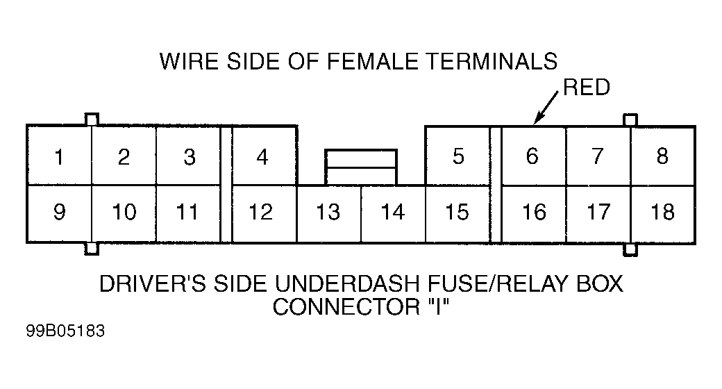
- Using fused jumper wire, connect between driver's under-dash fuse/relay box connector "I" wire side of female terminal No. 6 (Red wire) and ground. See Fig 5. With combination light switch in parking light or headlight position, dash lights should illuminate at full brightness. If dash lights do not illuminate a full brightness, check for open in Red wire between driver's under-dash fuse/relay box and combination light switch. Repair as necessary.
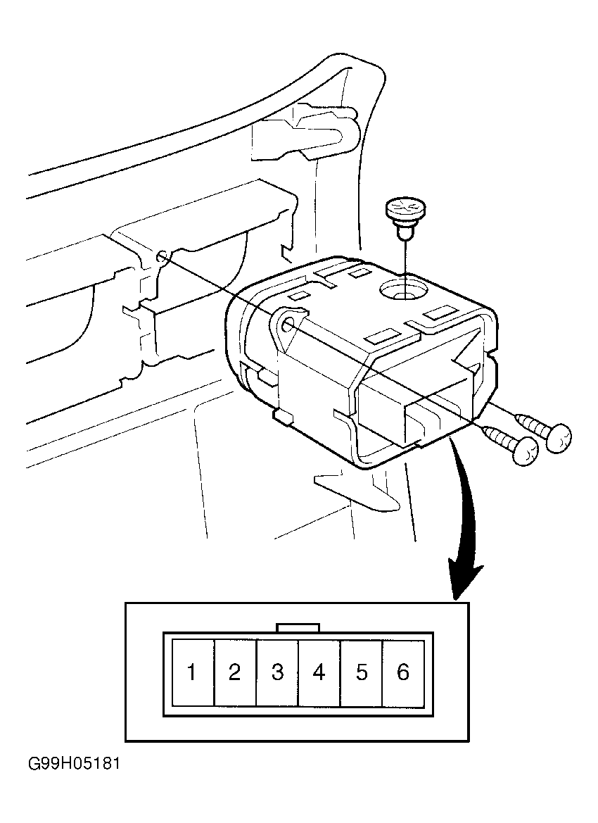 Courtesy of AMERICAN HONDA MOTOR CO., INC.
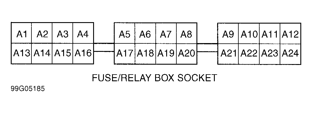 Courtesy of AMERICAN HONDA MOTOR CO., INC.
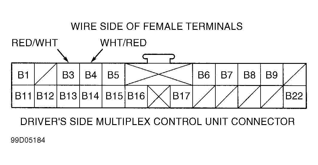 Courtesy of AMERICAN HONDA MOTOR CO., INC.
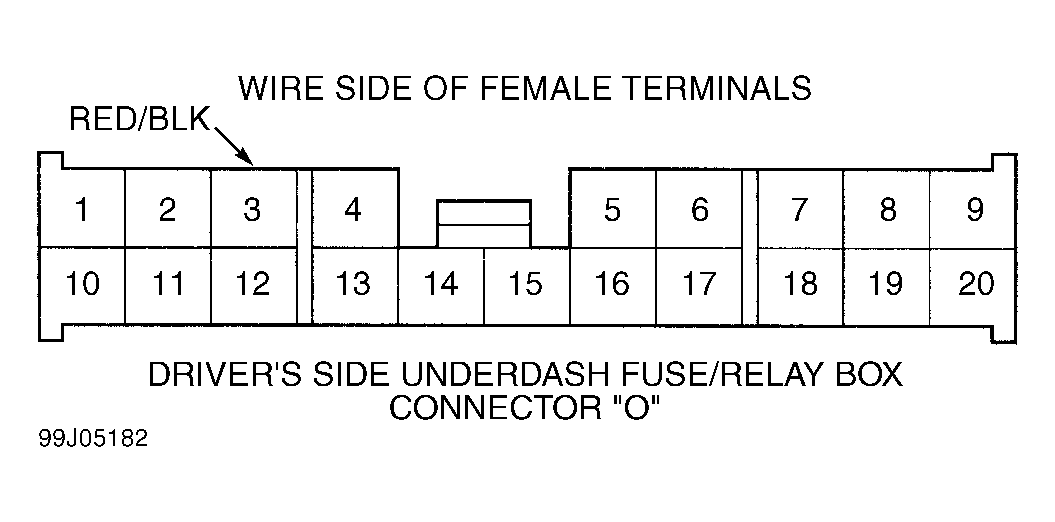 Courtesy of AMERICAN HONDA MOTOR CO., INC.
 Courtesy of AMERICAN HONDA MOTOR CO., INC.