Pinpoint Test P: The Brake Warning Indicator Is Always On
Instrumentation, Message Center and Warning Chimes
Pinpoint Test P: The Brake Warning Indicator Is Always On
Refer to Wiring Diagram Set 60, Instrument Cluster for schematic and connector information Electrical Diagrams.
Normal Operation
The Instrument Cluster (IC) uses 3 basic messaged inputs to control the brake warning indicator. The first 2 are the parking brake switch and the brake fluid level switch. The third is for the Electronic Brake Distribution (EBD), controlled by the ABS. The parking brake switch and the brake fluid level switch status are sent from the Smart Junction Box (SJB) over the Medium Speed Controller Area Network (MS-CAN) communication bus. The EBD (Electronic Brake Distribution) message is sent from the ABS module over the High Speed Controller Area Network (HS-CAN) communication bus lines. The parking brake switch is hardwired to the SJB (Smart Junction Box) through the parking brake input circuit. The brake fluid level switch is hardwired to the SJB (Smart Junction Box) through the signal circuit and return circuit. When the parking brake is applied, the parking brake switch closes to ground through the ground circuit, providing a ground to the SJB (Smart Junction Box) and pulling the parking brake input circuit low. When a low brake fluid level condition exists, the low brake fluid level switch closes to ground, pulling the brake fluid level input circuit low. The SJB (Smart Junction Box) monitors the parking brake and low brake fluid level inputs and sends the IC (Instrument Cluster) a message to turn on the brake warning indicator when the parking brake is applied or the brake fluid is low. When the ABS module detects a base brake system concern or other ABS related concerns that affect the EBD (Electronic Brake Distribution) function, the ABS module sends a message to the IC (Instrument Cluster) to illuminate both the ABS warning indicator and the brake warning indicator.
If the brake fluid level or parking brake status messages are missing or deemed invalid by the IC (Instrument Cluster) for more than 5 seconds, the IC (Instrument Cluster) sets DTC U0140 and defaults the brake warning indicator on. If the EBD (Electronic Brake Distribution) message is missing or invalid, the IC (Instrument Cluster) sets DTC U0121 and defaults the brake warning indicator on. If the IC (Instrument Cluster) does not receive the ABS status message from the ABS module or the message is deemed invalid by the IC (Instrument Cluster) for greater than 5 seconds, the IC (Instrument Cluster) sets DTC U0121 and defaults the ABS warning indicator on.
- DTC B2479 (Park Brake Switch Circuit Short to Ground)- sets on-demand if the SJB (Smart Junction Box) detects a short to ground on the parking brake input circuit during the module self-test.
- DTC C1125 (Brake Fluid Level Sensor Input Circuit Failure)- a continuous and on-demand DTC that sets in the SJB (Smart Junction Box) if an open is detected on the brake fluid level input circuit or return circuit or if a short to ground is detected on the input circuit.
NOTE: If DTC U0140 is set in the IC (Instrument Cluster), other symptoms may also be present such as Tire Pressure Monitoring System (TPMS), instrument panel backlighting, and door ajar indication.
NOTE: Both the ABS warning indicator and the brake warning indicator illuminate if the input to turn on the brake warning indicator is received from the ABS module.
This pinpoint test is intended to diagnose the following:
- Wiring, terminals or connectors
- Parking brake switch
- Brake fluid level switch (part of the master cylinder)
- ABS concern
- SJB (Smart Junction Box)
- IC (Instrument Cluster)
PINPOINT TEST P : THE BRAKE WARNING INDICATOR IS ALWAYS ON
NOTICE: Use the correct probe adapter(s) when making measurements. Failure to use the correct probe adapter(s) may damage the connector.
P1 RETRIEVE THE RECORDED DTCs FROM THE IC (Instrument Cluster) SELF-TEST
- Check for recorded IC (Instrument Cluster) DTCs from the self-test.
Are any DTCs recorded?
Yes
For DTC U0140, GO to Pinpoint Test AY. Pinpoint Test AY: DTC U0037 And U0140
For DTC U0121, GO to Pinpoint Test AW. Pinpoint Test AW: DTC U0121
For all other DTCs, REFER to DTC Charts. Instrumentation, Message Center and Warning Chimes
No
GO to P2.
P2 RETRIEVE THE RECORDED DTCs FROM THE ABS MODULE SELF-TEST
- Check for recorded ABS module DTCs from the self-test.
Are any DTCs recorded?
Yes
REFER to Antilock Brakes / Traction Control Systems.
No
GO to P3.
P3 RETRIEVE THE RECORDED DTCs FROM THE SJB (Smart Junction Box) SELF-TEST
- Check for recorded SJB (Smart Junction Box) DTCs from the self-test.
Are any DTCs recorded?
Yes
If DTC B2479 is retrieved, GO to P5.
If DTC C1125 is retrieved, GO to P8.
No
GO to P4.
P4 CARRY OUT THE IC (Instrument Cluster) INDICATOR LAMP CONTROL ACTIVE COMMAND USING THE SCAN TOOL
- Ignition ON.
- Enter the following diagnostic mode on the scan tool: IC (Instrument Cluster) DataLogger.
- Select the IC (Instrument Cluster) brake warning lamp (BRK_LAMP) active command on and off. Observe the brake warning indicator.
Does the brake warning indicator turn off when commanded off?
Yes
INSTALL a new ABS module. TEST the system for normal operation.
No
INSTALL a new IC (Instrument Cluster). REFER to Instrument Cluster (IC) . TEST the system for normal operation.
P5 CHECK THE PARKING BRAKE SWITCH PID
- Enter the following diagnostic mode on the scan tool: SJB (Smart Junction Box) DataLogger.
- Monitor the SJB (Smart Junction Box) (PRK_BRAKE) PID while applying and releasing the parking brake.
Does the PID agree with the parking brake position?
Yes
GO to P12.
No
GO to P6.
P6 CHECK THE PARKING BRAKE SWITCH
- Disconnect: Parking Brake Switch C2015.
- Observe the brake warning indicator.
Does the brake warning indicator continue to illuminate?
Yes
GO to P7.
No
INSTALL a new parking brake switch. REPEAT the self-test. CLEAR the DTCs.
P7 CHECK THE PARKING BRAKE INPUT CIRCUIT FOR A SHORT TO GROUND
- Ignition OFF.
- Disconnect: SJB (Smart Junction Box) C2280C.
- Measure the resistance between the SJB (Smart Junction Box) C2280C-1, circuit CCB01 (VT/BN), harness side and ground.
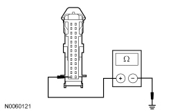
Is the resistance greater than 10,000 ohms?
Yes
GO to P12.
No
REPAIR circuit CCB01 (VT/BN) for a short to ground. REPEAT the self-test. CLEAR the DTCs.
P8 CHECK THE BRAKE FLUID LEVEL SWITCH INPUT TO THE SJB (Smart Junction Box)
- Ignition OFF.
- Disconnect: Brake Fluid Level Switch C124.
- Connect a fused jumper wire between the brake fluid level switch C124-3, circuit CMC19 (GY/VT), harness side and the brake fluid level switch C124-2, circuit RMC19 (YE/GY), harness side.
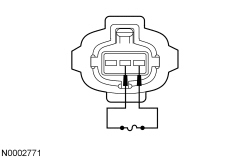
- Ignition ON.
Does the brake warning indicator turn off?
Yes
INSTALL a new master cylinder. REPEAT the self-test. CLEAR the DTCs.
No
REMOVE the jumper wire. GO to P9.
P9 CHECK THE BRAKE FLUID LEVEL INPUT CIRCUIT FOR AN OPEN
- Ignition OFF.
- Disconnect: SJB (Smart Junction Box) C2280F.
- Measure the resistance between the SJB (Smart Junction Box) C2280F-9, circuit CMC19 (GY/VT), harness side and the brake fluid level switch C124-3, circuit CMC19 (GY/VT), harness side.
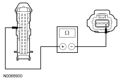
Is the resistance less than 5 ohms?
Yes
GO to P10.
No
REPAIR circuit CMC19 (GY/VT) for an open. TEST the system for normal operation.
P10 CHECK THE BRAKE FLUID LEVEL RETURN CIRCUIT FOR AN OPEN
- Measure the resistance between the SJB (Smart Junction Box) C2280F-22, circuit RMC19 (YE/GY), harness side and the brake fluid level switch C124-2, circuit RMC19 (YE/GY), harness side.
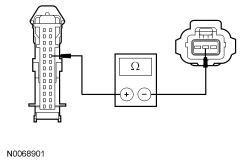
Is the resistance less than 5 ohms?
Yes
GO to P11.
No
REPAIR circuit RMC19 (YE/GY) for an open. TEST the system for normal operation.
P11 CHECK THE BRAKE FLUID LEVEL INPUT AND RETURN CIRCUITS FOR A SHORT TO GROUND
- Measure the resistance between the SJB (Smart Junction Box) C2280F-9, circuit CMC19 (GY/VT), harness side and ground; and between the SJB (Smart Junction Box) C2280F-22, circuit RMC19 (YE/GY), harness side and ground.
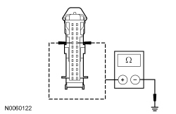
Are the resistances greater than 10,000 ohms?
Yes
GO to P12.
No
REPAIR the circuit in question. TEST the system for normal operation.
P12 CHECK FOR CORRECT SJB (Smart Junction Box) OPERATION
- Disconnect all the SJB (Smart Junction Box) connectors.
- Check for:
- corrosion
- damaged pins
- pushed-out pins
- Connect all the SJB (Smart Junction Box) connectors and make sure they seat correctly.
- Operate the system and verify that the concern is still present.
Is the concern still present?
Yes
INSTALL a new SJB (Smart Junction Box). TEST the system for normal operation.
No
The system is operating correctly at this time. The concern may have been caused by a loose or corroded connector.