Pinpoint Test G: No Sound From All Speakers
Information and Entertainment System
Pinpoint Test G: No Sound From All Speakers - Navigator
Refer to Wiring Diagram Set 130, Audio System/Navigation for schematic and connector information Electrical Diagrams.
Normal Operation
When the key is in START, the Audio Front Control Module (ACM) receives voltage on the START signal circuit. The ACM (Audio Front Control Module) then mutes the speaker output to prevent voltage spikes from producing a popping noise through the speakers. However, a short to voltage on this circuit causes the ACM (Audio Front Control Module) output to be continuously muted.
If a speaker circuit fault DTC is set in the ACM (Audio Front Control Module), the cause of the concern is a short to ground or short to voltage in an individual speaker circuit, which has caused the ACM (Audio Front Control Module) overload protection to activate. If a speaker circuit fault DTC is present, refer to DTC Charts. Accessories and Optional Equipment
To enable the audio Digital Signal Processing (DSP) module, the ACM (Audio Front Control Module) sends voltage through the enable/clip circuit. The circuit acts as both an output (to enable the amplifier) and an input (to detect an amplifier overload condition). The voltage sent by the ACM (Audio Front Control Module) passes through a variable resistor in the audio DSP (Digital Signal Processing) module, then to ground. As the amplifier (integral to the audio DSP (Digital Signal Processing) module) reaches maximum output, the resistance in the variable resistor decreases. This decreases the voltage drop, resulting in the ACM (Audio Front Control Module) detecting a higher voltage on the enable/clip circuit. When the voltage reaches the clip threshold, the ACM (Audio Front Control Module) clips the audio output signal to the audio DSP (Digital Signal Processing) module (heard as distortion), in order to prevent damage to the amplifier and speakers.
The enable/clip status is based on the following voltages, as detected by the ACM (Audio Front Control Module) :
- Less than 0.4 volt: amplifier disabled
- Between 3.8 and 6.7 volts: amplifier enabled
- Greater than 8.5 volts: amplifier clipped
- DTC U0238 (Lost Communication With Digital Audio Control Module "D" (DSP (Digital Signal Processing)))- set by the non-navigation ACM (Audio Front Control Module) when it is missing the audio DSP (Digital Signal Processing) module status message for greater than 5 seconds with the ignition in the RUN position. Audio may still be produced, but the sound quality may be compromised.
- DTC U0238:00 (Lost Communication With Digital Audio Control Module "D": No Sub Type Information)- set by the navigation ACM (Audio Front Control Module) when it is missing the audio DSP (Digital Signal Processing) module status message for greater than 5 seconds with the ignition in the RUN position. Audio may still be produced, but the sound quality may be compromised.
This pinpoint test is intended to diagnose the following:
- Fuse
- Wiring, terminals or connectors
- Audio DSP (Digital Signal Processing) module
- ACM (Audio Front Control Module)
PINPOINT TEST G : NO SOUND FROM ALL SPEAKERS - NAVIGATOR
NOTICE: Use the correct probe adapter(s) when making measurements. Failure to use the correct probe adapter(s) may damage the connector.
NOTE: Failure to disconnect the battery when instructed will result in false resistance readings.
G1 CHECK THE START SIGNAL CIRCUIT FOR A SHORT TO VOLTAGE
- Ignition OFF.
- Disconnect: ACM (Audio Front Control Module) C240A.
- Measure the voltage between the ACM (Audio Front Control Module) C240A-15, circuit CBP28 (GY/VT), harness side and ground.
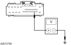
Is any voltage present?
Yes
REPAIR the circuit. TEST the system for normal operation.
No
GO to G2.
G2 CHECK THE AUDIO DSP (Digital Signal Processing) MODULE VOLTAGE SUPPLY
- Ignition OFF.
- Disconnect: Audio DSP (Digital Signal Processing) Module C2364A.
- Measure the voltage between the audio DSP (Digital Signal Processing) module, harness side and ground as follows:
Positive Meter Lead Negative Meter Lead Circuit C2364A-9 Ground SBP38 (BN/RD) C2364A-10 Ground SBP38 (BN/RD) C2364A-11 Ground SBP40 (VT/RD) C2364A-12 Ground SBP40 (VT/RD)
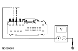
Are the voltages greater than 10 volts?
Yes
GO to G3.
No
VERIFY the Smart Junction Box (SJB) fuse 38 (20A) or fuse 40 (20A) is OK. If OK, REPAIR the circuit in question. TEST the system for normal operation. If not OK, REFER to the Wiring Diagrams to identify the possible causes of the circuit short Electrical Diagrams.
G3 CHECK THE AUDIO DSP (Digital Signal Processing) MODULE GROUND CIRCUITS FOR CONTINUITY
- Disconnect: Negative Battery Cable.
- Measure the resistance between the audio DSP (Digital Signal Processing) module, harness side and ground as follows:
Positive Meter Lead Negative Meter Lead Circuit C2364A-21 Ground GD114 (BK/BU) C2364A-22 Ground GD114 (BK/BU) C2364A-23 Ground GD114 (BK/BU) C2364A-24 Ground GD114 (BK/BU)
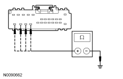
Are the resistances less than 5 ohms?
Yes
GO to G4.
No
REPAIR the circuit in question. TEST the system for normal operation.
G4 CHECK THE AUDIO DSP (Digital Signal Processing) MODULE ENABLE CIRCUIT FOR CORRECT VOLTAGE
- Connect: Negative Battery Cable.
- Connect: Audio DSP (Digital Signal Processing) Module C2364A.
- Disconnect: Audio DSP (Digital Signal Processing) Module C2364C.
- Operate the audio system in radio tuner (AM/FM) mode.
- Measure the voltage between the audio DSP (Digital Signal Processing) module C2364C-3, circuit SME23 (VT/RD), harness side and ground.
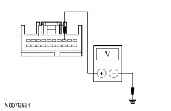
Is the voltage between 3.8 and 6.7 volts?
Yes
GO to G8.
No
GO to G5.
G5 CHECK THE AUDIO DSP (Digital Signal Processing) MODULE ENABLE CIRCUIT FOR A SHORT TO VOLTAGE
- Disconnect: ACM (Audio Front Control Module) C240D.
- Ignition ON.
- Measure the voltage between the audio DSP (Digital Signal Processing) module C2364C-3, circuit SME23 (VT/RD), harness side and ground.
Is any voltage present?
Yes
REPAIR the circuit. TEST the system for normal operation.
No
GO to G6.
G6 CHECK THE AUDIO DSP (Digital Signal Processing) MODULE ENABLE CIRCUIT FOR AN OPEN OR SHORT TO GROUND
- Ignition OFF.
- Measure the resistance between the audio DSP (Digital Signal Processing) module C2364C-3, circuit SME23 (VT/RD), harness side and the ACM (Audio Front Control Module) C240D-4, circuit SME23 (VT/RD), harness side; and between the audio DSP (Digital Signal Processing) module C2364C-3, circuit SME23 (VT/RD), harness side and ground.
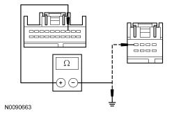
Is the resistance less than 5 ohms between the audio DSP (Digital Signal Processing) module and the ACM (Audio Front Control Module), and greater than 10,000 ohms between the audio DSP (Digital Signal Processing) module and ground?
Yes
GO to G7.
No
REPAIR the circuit. TEST the system for normal operation.
G7 CHECK FOR CORRECT ACM (Audio Front Control Module) OPERATION
- Ignition OFF.
- Connect: All Disconnected Connectors.
- Disconnect all the ACM (Audio Front Control Module) connectors.
- Check for:
- corrosion
- damaged pins
- pushed-out pins
- Connect all the ACM (Audio Front Control Module) connectors and make sure they seat correctly.
- Operate the system and determine if the concern is still present.
Is the concern still present?
Yes
INSTALL a new ACM (Audio Front Control Module). REFER to Audio Control Module (ACM) . TEST the system for normal operation.
No
The system is operating correctly at this time. The concern may have been caused by a loose or corroded connector.
G8 CHECK FOR CORRECT AUDIO DSP (Digital Signal Processing) MODULE OPERATION
- Ignition OFF.
- Connect: All Disconnected Connectors.
- Disconnect all the audio DSP (Digital Signal Processing) module connectors.
- Check for:
- corrosion
- damaged pins
- pushed-out pins
- Connect all the audio DSP (Digital Signal Processing) module connectors and make sure they seat correctly.
- Operate the system and determine if the concern is still present.
Is the concern still present?
Yes
INSTALL a new audio DSP (Digital Signal Processing) module. REFER to Audio Digital Signal Processing (DSP) Module . TEST the system for normal operation.
No
The system is operating correctly at this time. The concern may have been caused by a loose or corroded connector.