Steering Pad Switch Circuit
CRUISE CONTROL: LANE DEPARTURE ALERT SYSTEM: Steering Pad Switch Circuit
- Steering Pad Switch Circuit
DESCRIPTION
The driving support ECU receives lane departure alert system on/off signals from the steering pad switch assembly.
WIRING DIAGRAM
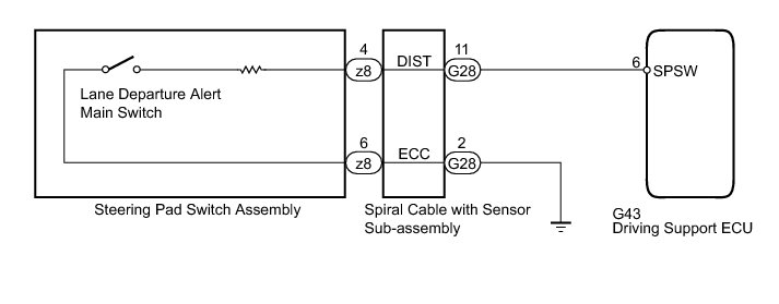
INSPECTION PROCEDURE
PROCEDURE
1. READ VALUE USING TECHSTREAM (LANE DEPARTURE ALERT MAIN SWITCH)
(a) Use the Data List to check if the lane departure alert main switch is functioning properly Scan Tool Testing and Procedures.
Lane Keeping Assist

OK:
On screen, item changes between ON and OFF according to above chart.
NG -- INSPECT STEERING PAD SWITCH ASSEMBLY
OK -- PROCEED TO NEXT SUSPECTED AREA SHOWN IN PROBLEM SYMPTOMS TABLE Symptom Related Diagnostic Procedures
2. INSPECT STEERING PAD SWITCH ASSEMBLY
(a) Remove the steering pad switch assembly Removal.
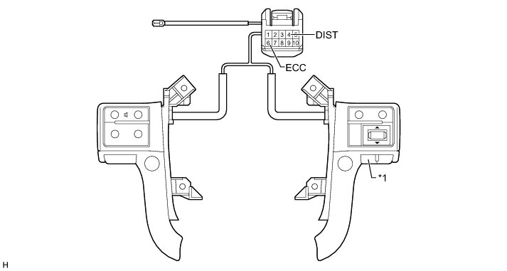
Text in Illustration

Standard Resistance:

NG -- REPLACE STEERING PAD SWITCH ASSEMBLY Removal
OK -- Continue to next step.
3. INSPECT SPIRAL WITH SENSOR CABLE SUB-ASSEMBLY
(a) Remove the spiral with sensor cable sub-assembly Removal.
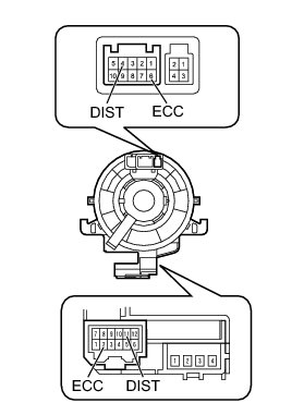
(b) If there are any defects as follows, replace the spiral with sensor cable with a new one: scratches, cracks, dents or chips in the connector or spiral with sensor cable.
(c) Check the spiral with sensor cable.
(1) Set the spiral with sensor cable to the center position Installation.
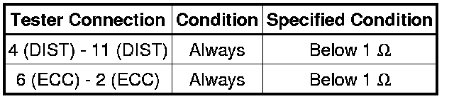
(2) Rotate the spiral with sensor cable 2.5 times clockwise and measure the resistance according to the value(s) in the table below. Then rotate the spiral with sensor cable 5 times counterclockwise and measure the resistance according to the value(s) in the table below.
NOTICE:
As the spiral with sensor cable may break, do not rotate the spiral with sensor cable more than the specified amount.
Standard Resistance:
(3) Set the spiral with sensor cable to the center position and rotate the spiral with sensor cable 2.5 times clockwise. Then, while rotating the spiral with sensor cable 5 times counterclockwise, measure the resistance according to the value(s) in the table below.
Standard Resistance:
NG -- REPLACE SPIRAL WITH SENSOR CABLE SUB-ASSEMBLY Removal
OK -- Continue to next step.
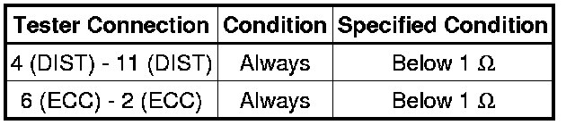
4. CHECK HARNESS AND CONNECTOR (SPIRAL WITH SENSOR CABLE SUB-ASSEMBLY - DRIVING SUPPORT ECU AND BODY GROUND)
(a) Disconnect the G28 spiral with sensor cable sub-assembly connector.
(b) Disconnect the G43 driving support ECU connector.
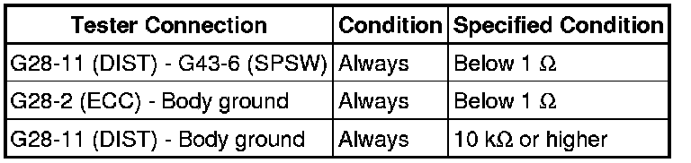
(c) Measure the resistance according to the value(s) in the table below.
Standard Resistance:
NG -- REPAIR OR REPLACE HARNESS OR CONNECTOR
OK -- REPLACE DRIVING SUPPORT ECU Removal