Illumination Circuit
NAVIGATION / MULTI INFO DISPLAY: NAVIGATION SYSTEM: Illumination Circuit
Illumination Circuit
DESCRIPTION
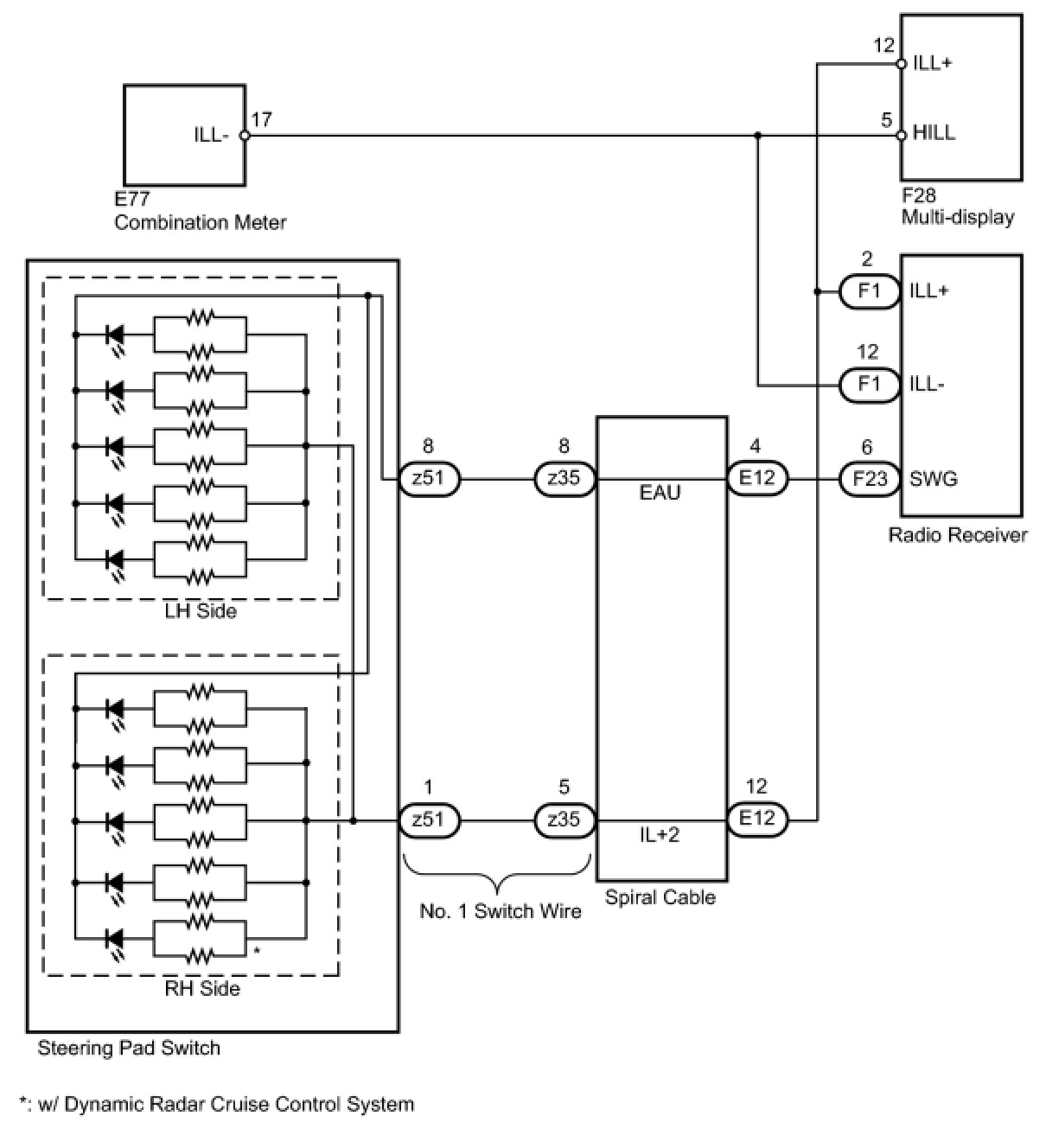
Power is supplied to the display and navigation module display, radio receiver and steering pad switch illumination when the light control switch is in the TAIL or HEAD position.
WIRING DIAGRAM
INSPECTION PROCEDURE
NOTICE:
The vehicle is equipped with an SRS (Supplemental Restraint System) which includes components such as airbags. Before servicing (including removal or installation of parts), be sure to read the Precaution in the Supplemental Restraint System Service Precautions.
PROCEDURE
1. CHECK ILLUMINATION
(a) Check if the illumination for the display and navigation module display, steering pad switch, glove box light, cigarette lighter, or other parts (seat heater switch, front seat memory switch, etc.) comes on when the light control switch is turned to the HEAD or TAIL position.
Result

D -- GO TO LIGHTING SYSTEM
C -- CHECK HARNESS AND CONNECTOR (DISPLAY AND NAVIGATION MODULE DISPLAY - BATTERY AND COMBINATION METER)
B -- CHECK HARNESS AND CONNECTOR (RADIO RECEIVER - COMBINATION METER)
A -- Continue to next step.
2. CHECK HARNESS AND CONNECTOR (BATTERY - SPIRAL CABLE)
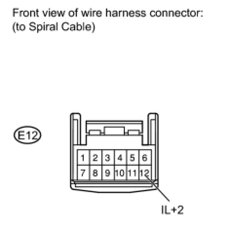
(a) Disconnect the E12 cable connector.
(b) Measure the voltage according to the value(s) in the table below.
Standard Voltage:

NG -- REPAIR OR REPLACE HARNESS OR CONNECTOR
OK -- Continue to next step.
3. CHECK NO. 1 SWITCH WIRE
(a) Disconnect the z35 cable connector.
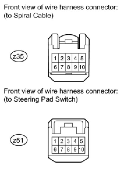
(b) Disconnect the z51 steering pad switch connector.
(c) Measure the resistance according to the valve(s) in the table below.
Standard Resistance:

NG -- CHECK NO. 1 SWITCH WIRE
OK -- Continue to next step.
4. CHECK STEERING PAD (STEERING PAD SWITCH)
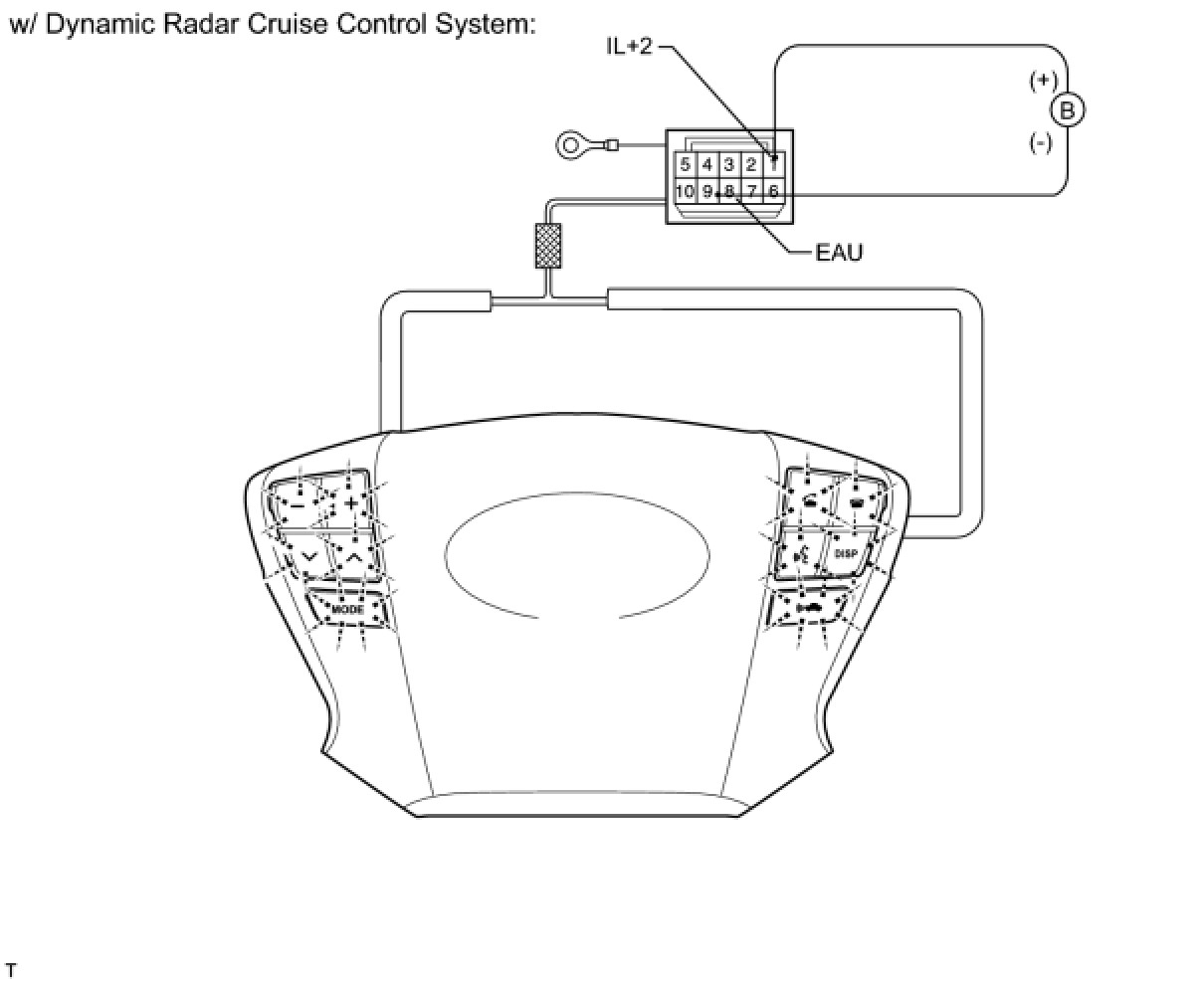
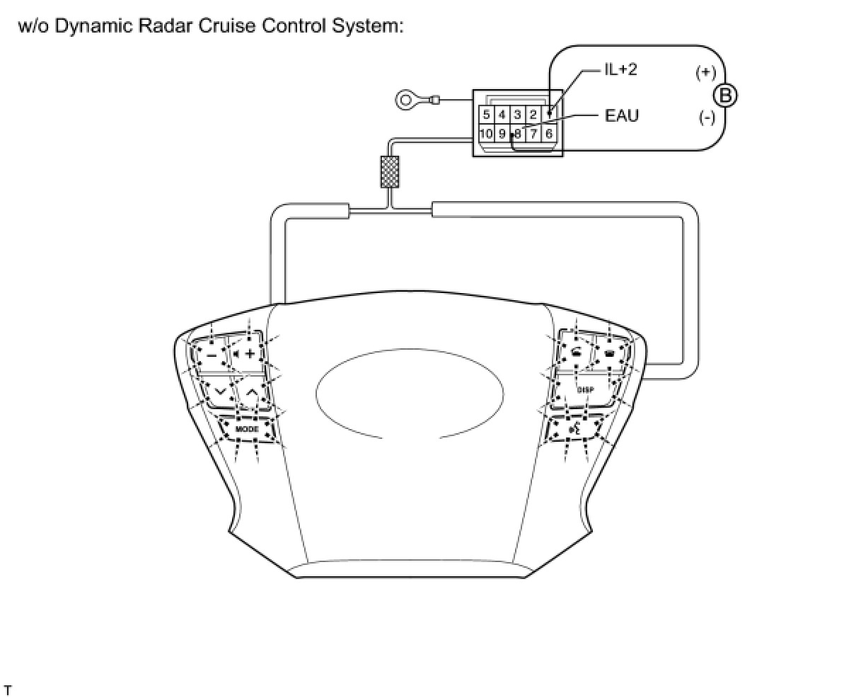
(a) Disconnect the z51 steering pad switch connector.
(b) Connect the positive (+) lead to terminal 1 (IL+2) and the negative (-) lead to terminal 8 (EAU) of the steering pad switch connector.
(c) Check if the illumination for the steering pad switch comes on.
OK:
Illumination for the steering pad switch comes on.
NG -- REPLACE STEERING PAD
OK -- Continue to next step.
5. INSPECT SPIRAL CABLE
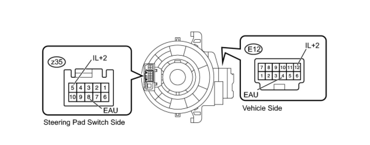
(a) Disconnect the cable connectors.
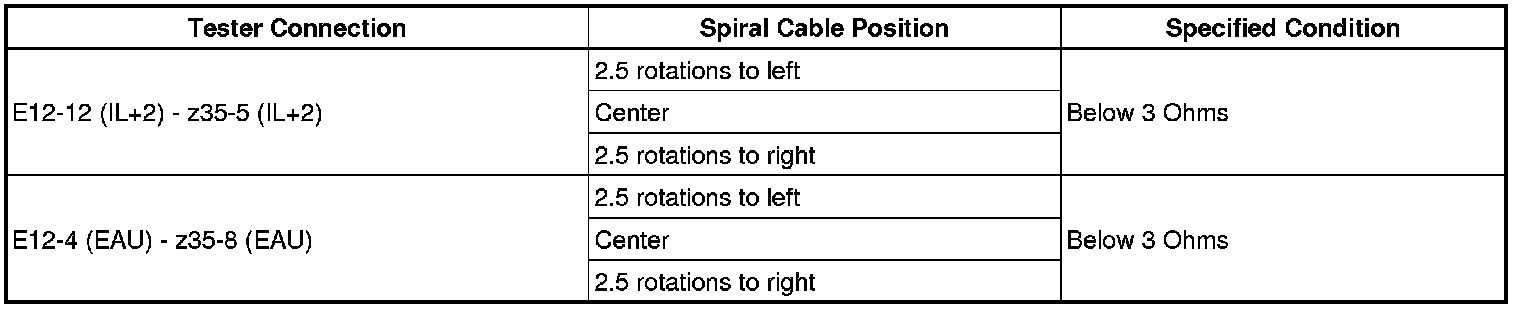
(b) Measure the resistance according to the value(s) in the table below.
Standard Resistance:
NOTICE:
The spiral cable is an important part of the SRS airbag system. Incorrect removal or installation of the spiral cable may prevent the airbag from deploying. Be sure to read the Precaution for the supplemental restraint system Service Precautions.
NG -- REPLACE SPIRAL CABLE SUB-ASSEMBLY
OK -- Continue to next step.
6. CHECK HARNESS AND CONNECTOR (SPIRAL CABLE - DISPLAY AND NAVIGATION MODULE DISPLAY AND RADIO RECEIVER)
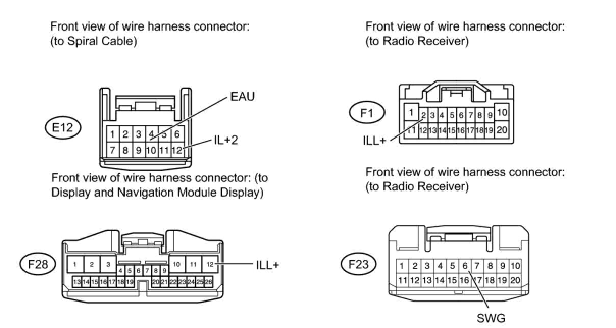
(a) Disconnect the E12 spiral cable connector.
(b) Disconnect the F1 and F23 receiver connectors.
(c) Disconnect the F28 display connector.
(d) Measure the resistance according to the value(s) in the table below.
Standard Resistance:

NG -- REPAIR OR REPLACE HARNESS OR CONNECTOR
OK -- PROCEED TO NEXT CIRCUIT INSPECTION SHOWN IN PROBLEM SYMPTOMS TABLE
7. CHECK HARNESS AND CONNECTOR (RADIO RECEIVER - COMBINATION METER)
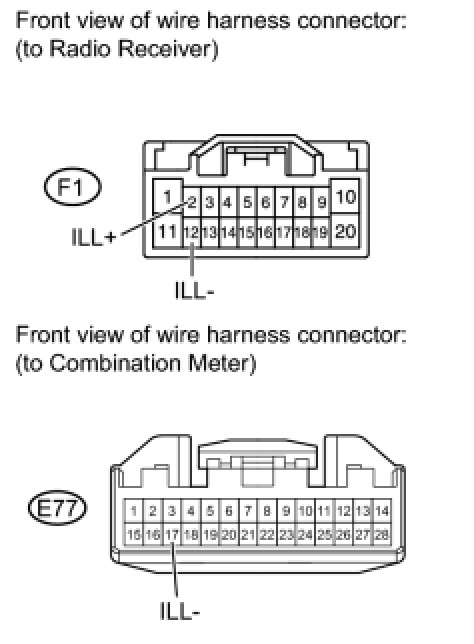
(a) Disconnect the F1 receiver connector.
(b) Disconnect the E77 meter connector.
(c) Measure the resistance according to the value(s) in the table below.
Standard Resistance:

(d) Measure the voltage according to the value(s) in the table below.
Standard Voltage:

NG -- REPAIR OR REPLACE HARNESS OR CONNECTOR
OK -- REPLACE RADIO RECEIVER ASSEMBLY
8. CHECK HARNESS AND CONNECTOR (DISPLAY AND NAVIGATION MODULE DISPLAY - BATTERY AND COMBINATION METER)
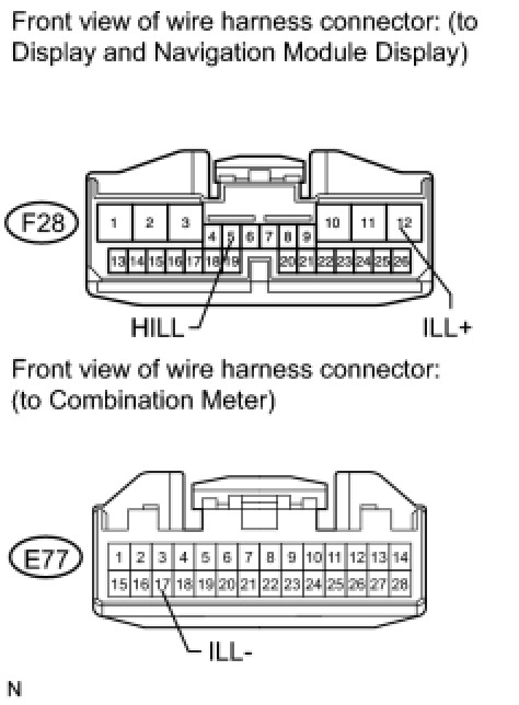
(a) Disconnect the F28 display connector.
(b) Disconnect the E77 meter connector.
(c) Measure the resistance according to the value(s) in the table below.
Standard Resistance:

(d) Measure the voltage according to the value(s) in the table below.
Standard Voltage:

NG -- REPAIR OR REPLACE HARNESS OR CONNECTOR
OK -- REPLACE DISPLAY AND NAVIGATION MODULE DISPLAY