Reverse Signal Circuit
PARK ASSIST / MONITORING: REAR VIEW MONITOR SYSTEM: Reverse Signal Circuit
Reverse Signal Circuit
DESCRIPTION
The multi-display receives a reverse signal from the park/neutral position switch.
This inspection procedure is for vehicles that are not equipped with a navigation system.
WIRING DIAGRAM
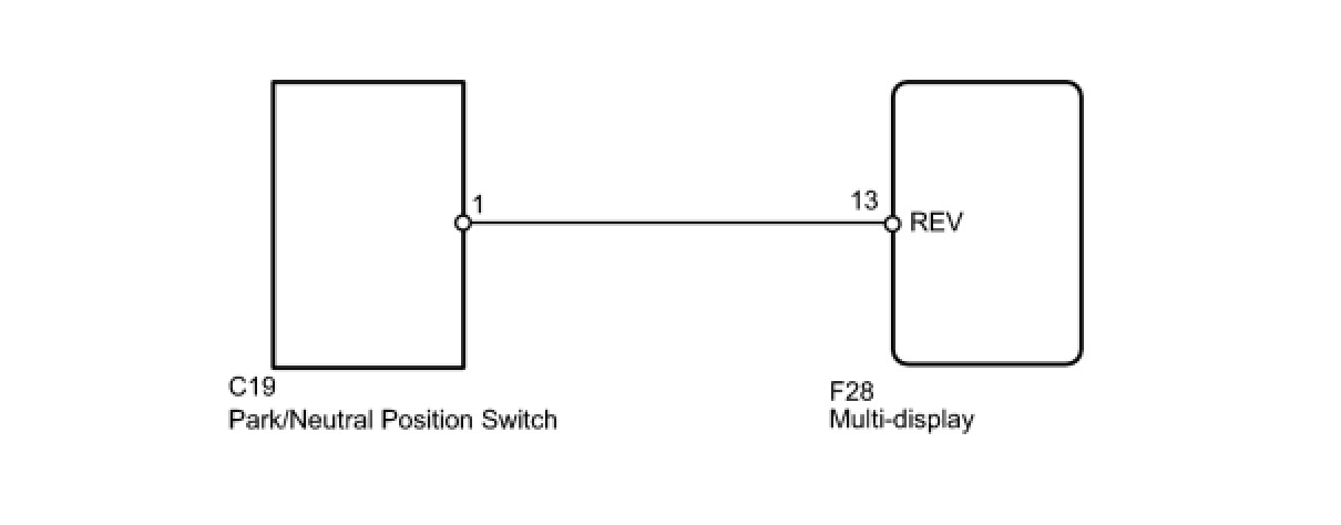
INSPECTION PROCEDURE
PROCEDURE
1. CHECK REVERSE SIGNAL (DISPLAY CHECK MODE)
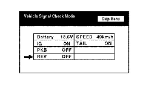
(a) Enter the "Display Check" mode and select "Vehicle Signal Check Mode" Operation Check.
(b) Check that the display changes between ON and OFF according to the shift lever operation.
OK:

HINT:
This display is updated once per second. As a result, it is normal for the display to lag behind the actual change in the switch.
NG -- CHECK PARK/NEUTRAL POSITION SWITCH
OK -- PROCEED TO NEXT CIRCUIT INSPECTION PROCEDURE IN PROBLEM SYMPTOMS TABLE
2. CHECK PARK/NEUTRAL POSITION SWITCH
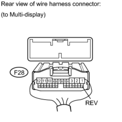
(a) Disconnect the F28 display connector.
(b) Measure the voltage according to the value(s) in the table below.
Standard Voltage:

NG -- CHECK HARNESS AND CONNECTOR (MULTI-DISPLAY - PARK/NEUTRAL POSITION SWITCH)
OK -- REPLACE MULTI-DISPLAY DISPLAY
3. CHECK HARNESS AND CONNECTOR (MULTI-DISPLAY - PARK/NEUTRAL POSITION SWITCH)
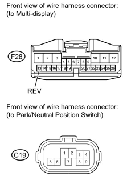
(a) Disconnect the F28 display connector.
(b) Disconnect the C19 position switch connector.
(c) Measure the resistance according to the value(s) in the table below.
Standard Resistance:

NG -- REPAIR OR REPLACE HARNESS OR CONNECTOR
OK -- REPLACE PARK/NEUTRAL POSITION SWITCH