Clearance Sonar Main Switch Circuit
PARK ASSIST / MONITORING: INTUITIVE PARKING ASSIST SYSTEM: Clearance Sonar Main Switch Circuit
Clearance Sonar Main Switch Circuit
DESCRIPTION
When the clearance sonar main switch turns on, the ON signal is input into the parking assist ECU.
WIRING DIAGRAM
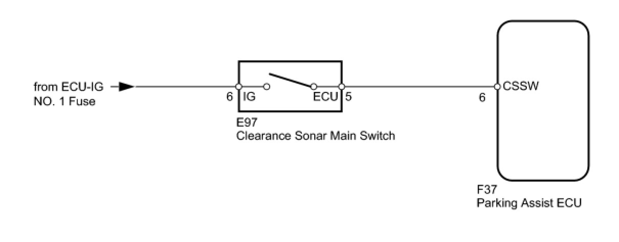
INSPECTION PROCEDURE
PROCEDURE
1. READ VALUE USING TECHSTREAM (CLEARANCE SONAR MAIN SWITCH)
(a) Check the Data List for proper functioning of the clearance sonar main switch.
Intuitive P/A

OK:
Techstream display changes according to operation of clearance sonar main switch.
NG -- INSPECT CLEARANCE SONAR MAIN SWITCH
OK -- PROCEED TO NEXT CIRCUIT INSPECTION SHOWN IN PROBLEM SYMPTOMS TABLE
2. INSPECT CLEARANCE SONAR MAIN SWITCH

(a) Remove the clearance sonar main switch Clearance Sonar Main Switch.
(b) Measure the resistance according to the value(s) in the table below.
Standard Resistance:

NG -- REPLACE CLEARANCE SONAR MAIN SWITCH
OK -- Continue to next step.
3. CHECK HARNESS AND CONNECTOR (MAIN SWITCH - ECU AND BATTERY)
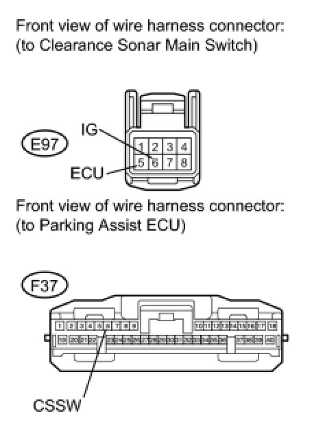
(a) Disconnect the E97 switch connector.
(b) Disconnect the F37 ECU connector.
(c) Measure the voltage according to the value(s) in the table below.
Standard Voltage:

(d) Measure the resistance according to the value(s) in the table below.
Standard Resistance:

NG -- REPAIR OR REPLACE HARNESS OR CONNECTOR
OK -- REPLACE PARKING ASSIST ECU