Instrument Panel Assembly
INSTRUMENT PANEL ASSEMBLY
REMOVAL
WARNING: ON VEHICLES EQUIPPED WITH AIRBAGS, DISABLE THE AIRBAG SYSTEM BEFORE ATTEMPTING ANY STEERING WHEEL, STEERING COLUMN, OR INSTRUMENT PANEL COMPONENT DIAGNOSIS OR SERVICE. DISCONNECT AND ISOLATE THE BATTERY NEGATIVE (GROUND) CABLE, THEN WAIT TWO MINUTES FOR THE AIRBAG SYSTEM CAPACITOR TO DISCHARGE BEFORE PERFORMING FURTHER DIAGNOSIS OR SERVICE. THIS IS THE ONLY SURE WAY TO DISABLE THE AIRBAG SYSTEM. FAILURE TO TAKE THE PROPER PRECAUTIONS COULD RESULT IN ACCIDENTAL AIRBAG DEPLOYMENT AND POSSIBLE PERSONAL INJURY.
NOTE: Before starting this procedure, be certain to turn the steering wheel until the front wheels are in the straight-ahead position.
1. Disconnect and isolate the battery negative cable.
2. Remove the trim from the right and left A-pillars. (Refer to Trim Panel). Trim Panel
3. Remove the top cover. Instrument Panel Top Cover
Fig. 23:
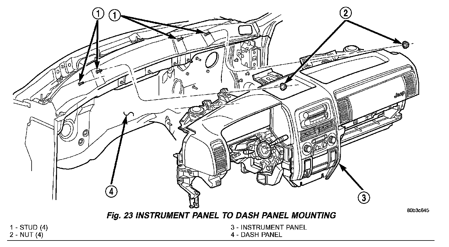
4. Remove the four nuts that secure the instrument panel to the studs on the dash panel near the windshield fence line (Fig. 23).
5. Remove the scuff plates from the right and left front door sills. Instrument Panel Top Cover
6. Remove the trim panels from the right and left inner cowl sides. Instrument Panel Top Cover
7. Remove the console from the floor panel transmission tunnel. Instrument Panel Top Cover
8. Remove the fuse cover from the junction block (JB).
9. Remove the cluster bezel. Instrument Panel Top Cover
10. Remove the steering column opening cover. Instrument Panel Top Cover
11. Remove the steering column bracket from the instrument panel steering column support bracket. Instrument Panel Top Cover
Fig. 24:
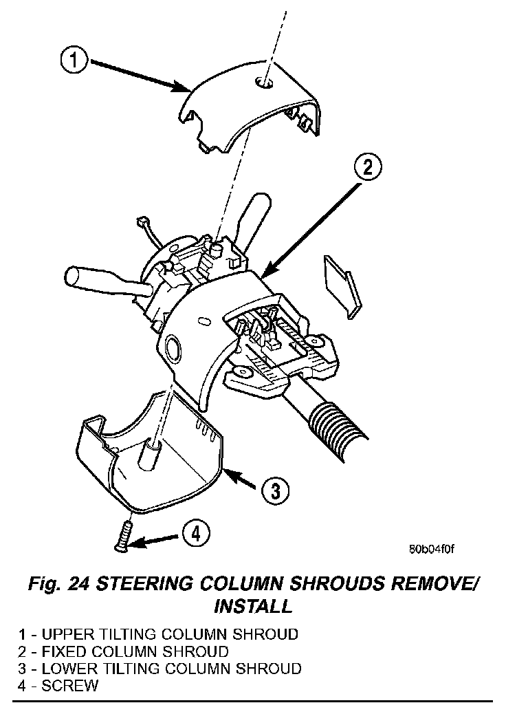
12. Remove the screw that secures the lower tilting steering column shroud to the steering column multi-function switch mounting housing (Fig. 24).
13. Unsnap the two halves of the tilting steering column shroud from each other and remove both halves from the steering column.
Fig. 25:
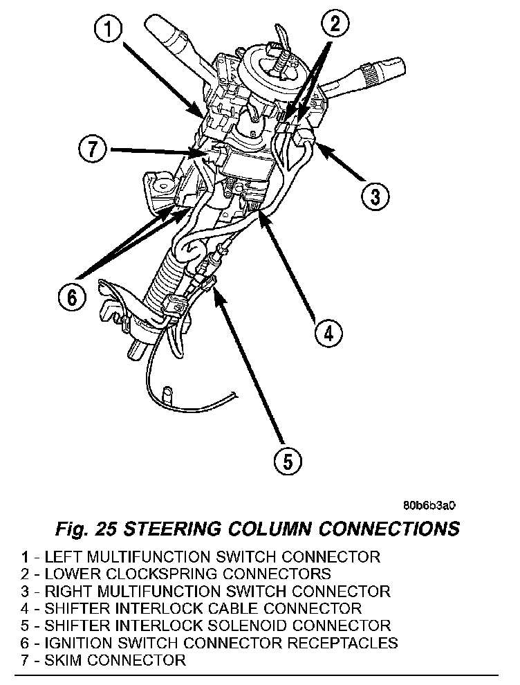
14. Disconnect the instrument panel wire harness connectors from the following steering column components (Fig. 25):
- the two lower clockspring connector receptacles
- the left multi-function switch connector receptacle
- the right multi-function switch connector receptacle
- the two ignition switch connector receptacles - the shifter interlock solenoid connector receptacle
- if equipped, the sentry key immobilizer module (SKIM) connector receptacle.
15. Turn the ignition switch to the On position, then release and remove the shifter interlock cable connector from the ignition lock housing receptacle.
16. Turn the ignition switch back to the Lock position to prevent steering wheel rotation and the loss of clockspring centering following steering column removal.
Fig. 26:
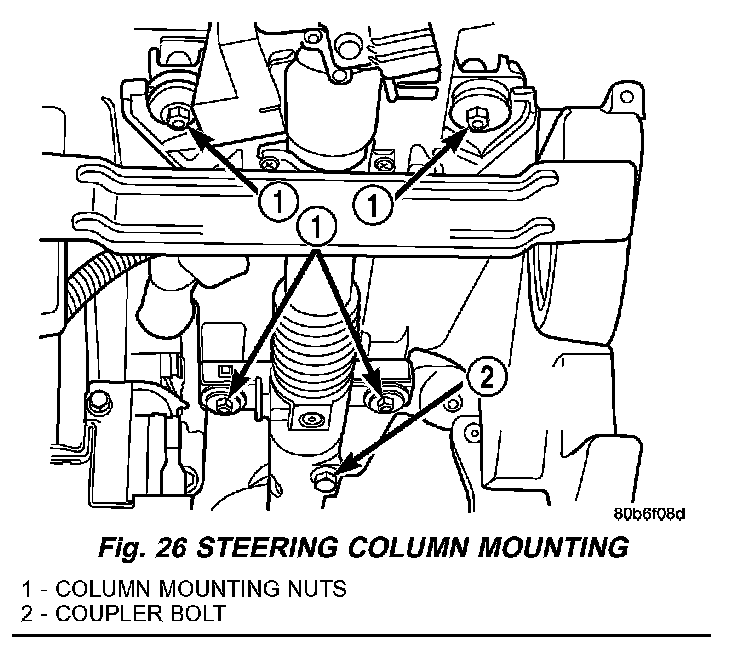
17. Remove the bolt that secures the coupler to the lower steering column shaft (Fig. 26).
18. Remove the four nuts that secure the steering column to the studs on the instrument panel steering column support bracket.
19. Remove the steering column from the instrument panel. Be certain that the steering wheel is locked and secured from rotation to prevent the loss of clockspring centering.
Fig. 27:
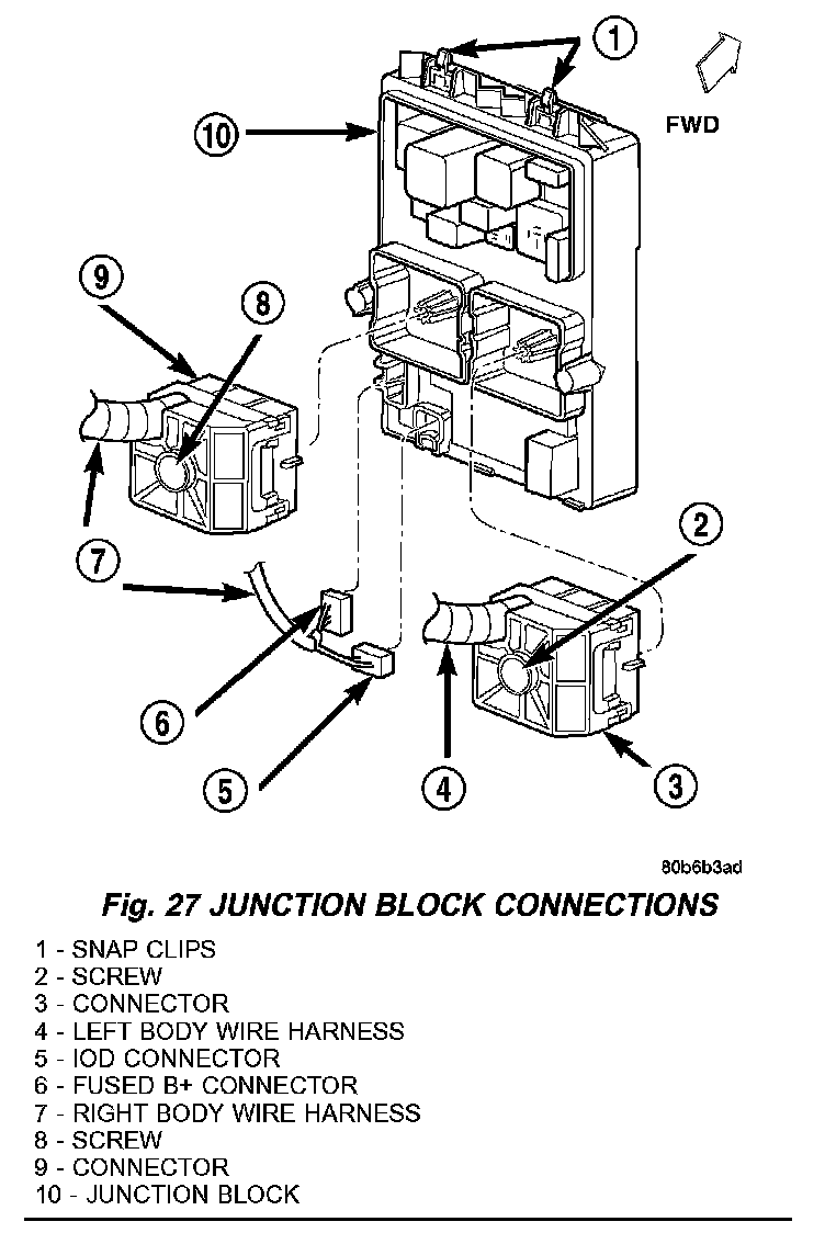
20. Disconnect the left and right body wire harness connectors, the ignition off draw (IOD) wire harness connector and the fused B(+) wire harness connector from the connector receptacles of the JB (Fig. 27).
Fig. 28:
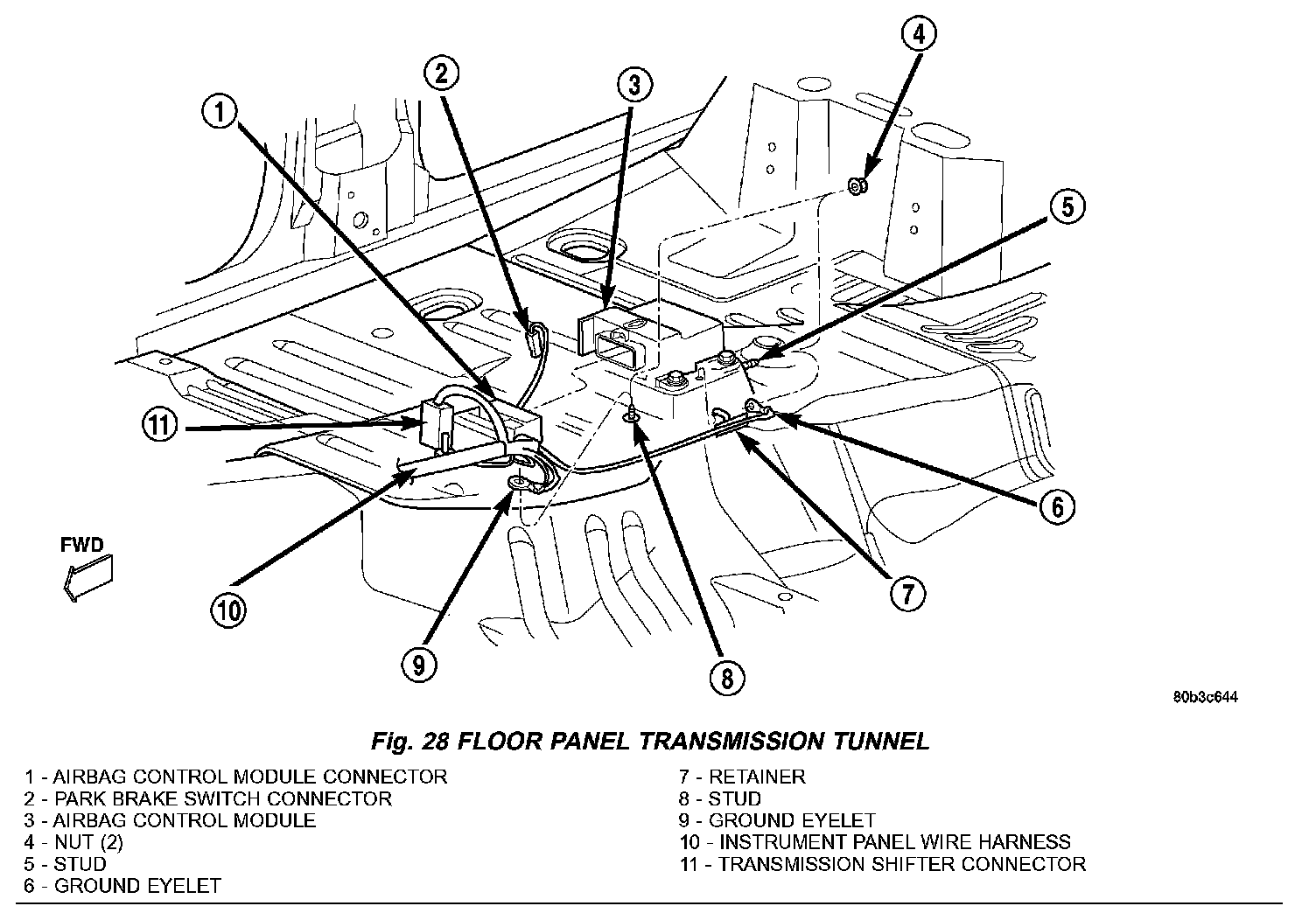
21. Disconnect the instrument panel wire harness connectors from the following floor panel transmission tunnel components (Fig. 28): - the airbag control module (ACM) connector receptacle - the park brake switch terminal - the transmission shifter connector receptacle.
22. Remove the two nuts that secure the instrument panel wire harness ground eyelets to the studs on the floor panel transmission tunnel in front of and behind the ACM.
23. Disengage the retainers that secure the instrument panel wire harness to the floor panel transmission tunnel.
24. Remove the instrument panel to center floor tunnel bracket from the instrument panel and the floor panel transmission tunnel.
25. Remove the one screw that secures the floor duct to the heater and air conditioner housing near the driver side of the floor panel transmission tunnel and remove the duct from the housing.
26. If the vehicle is equipped with the manual heating and air conditioning system, disconnect the vacuum harness connector located near the driver side of the floor panel transmission tunnel behind the driver side floor duct.
Fig. 29:
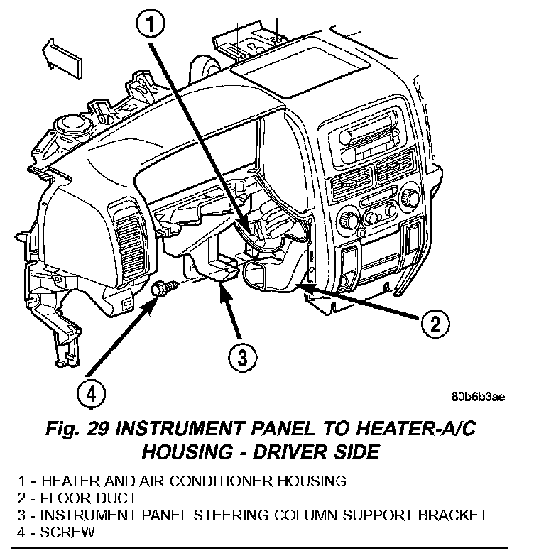
27. Remove the one screw that secures the instrument panel steering column support bracket to the driver side end of the heater and air conditioner housing (Fig. 29).
Fig. 30:
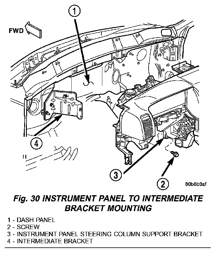
28. Remove the one screw that secures the instrument panel steering column support bracket to the intermediate bracket on the driver side dash panel (Fig. 30).
Fig. 31:
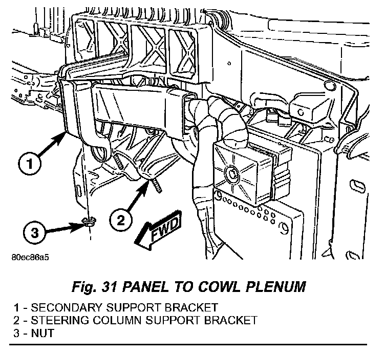
29. Remove the nut that secures the instrument panel steering column support bracket to the stud on the driver side cowl plenum panel (Fig. 31).
Fig. 32:
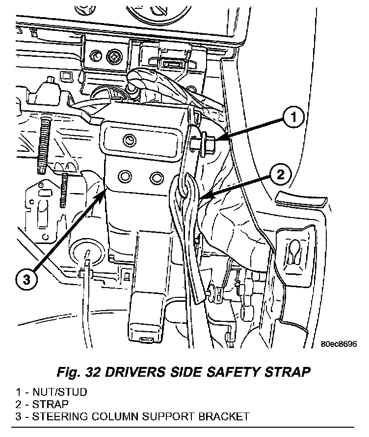
30. Remove the nut and disconnect the safety strap from the support bracket. (Fig. 32)
Fig. 33:
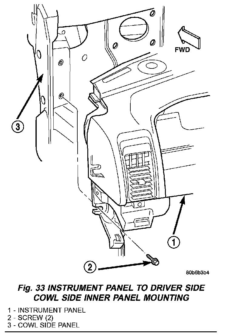
31. Remove the two screws that secure the instrument panel to the driver side cowl side inner panel (Fig. 33).
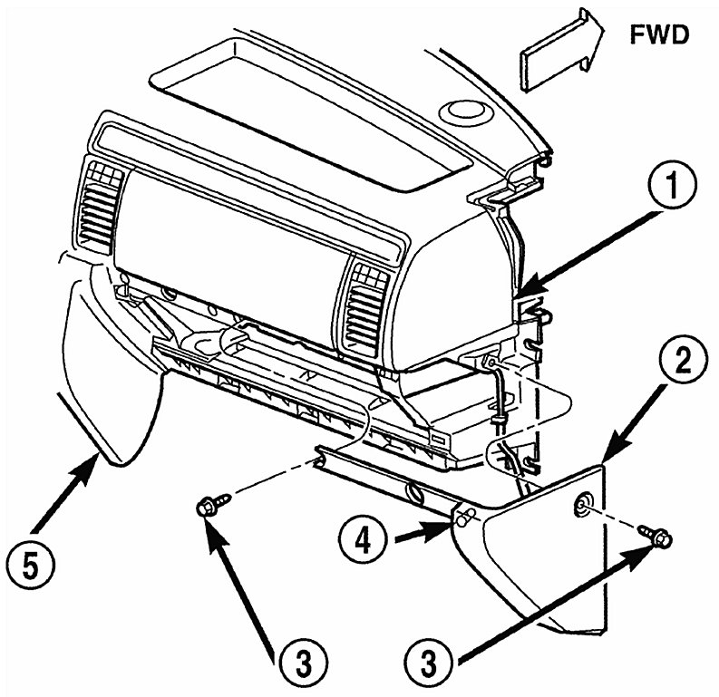
32. Remove the end cap.
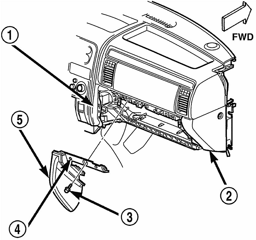
33. Remove the lower right center bezel.
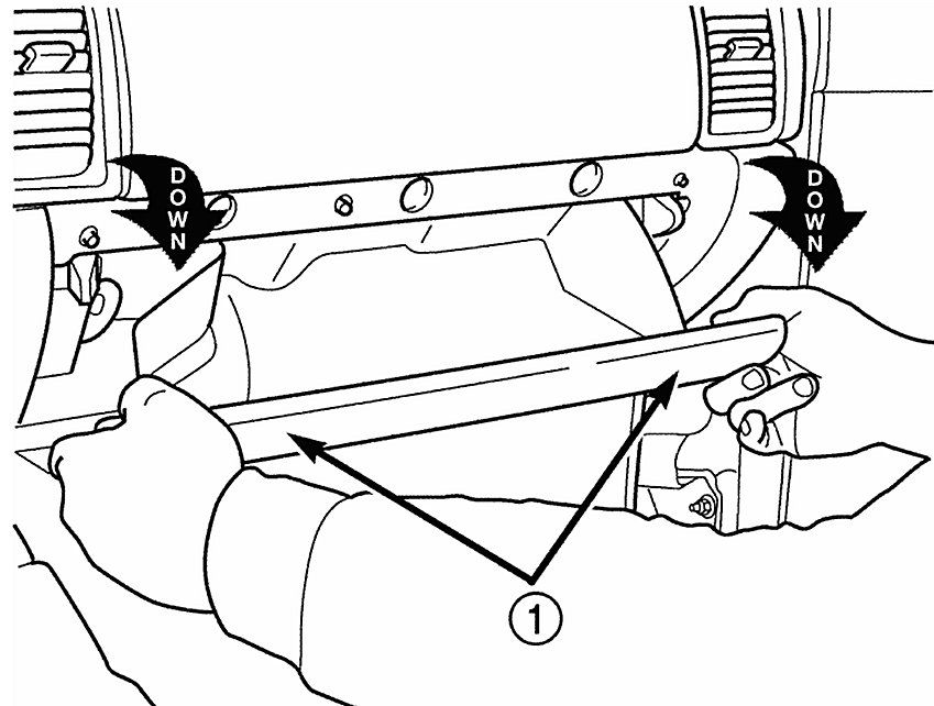
34. Remove the glove box. Service and Repair
Fig. 34:
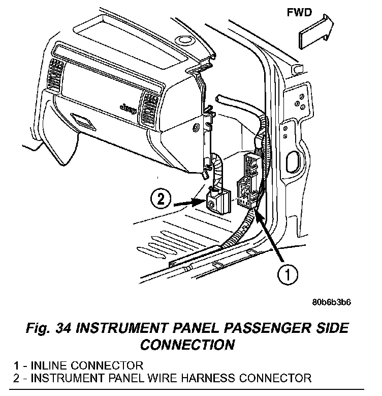
35. Disconnect the instrument panel wire harness connector from the lower cavity of the inline connector on the passenger side cowl side inner panel (Fig. 34).
36. Disconnect the two halves of the radio antenna coaxial cable connector near the right cowl side inner panel under the end of the instrument panel.
Fig. 35:
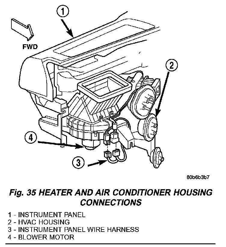
37. Disconnect the two instrument panel wire harness connectors from the two heater and air conditioner housing connectors located near the blower motor on the passenger side end of the housing (Fig. 35).
Fig. 36:
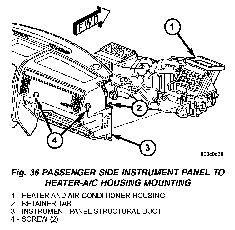
38. Remove the two screws that secure the passenger side instrument panel structural duct to the heater and air conditioner housing (Fig. 36).
Fig. 37:
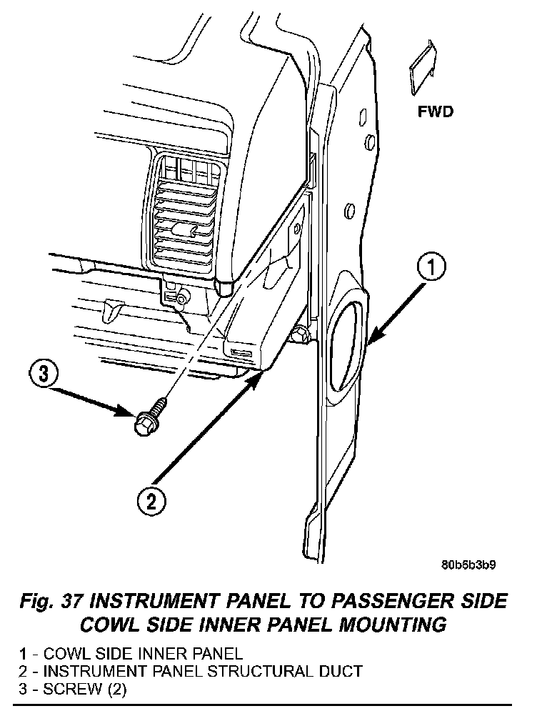
39. Remove the two screws that secure the instrument panel to the passenger side cowl side inner panel (Fig. 37).
Fig. 38:
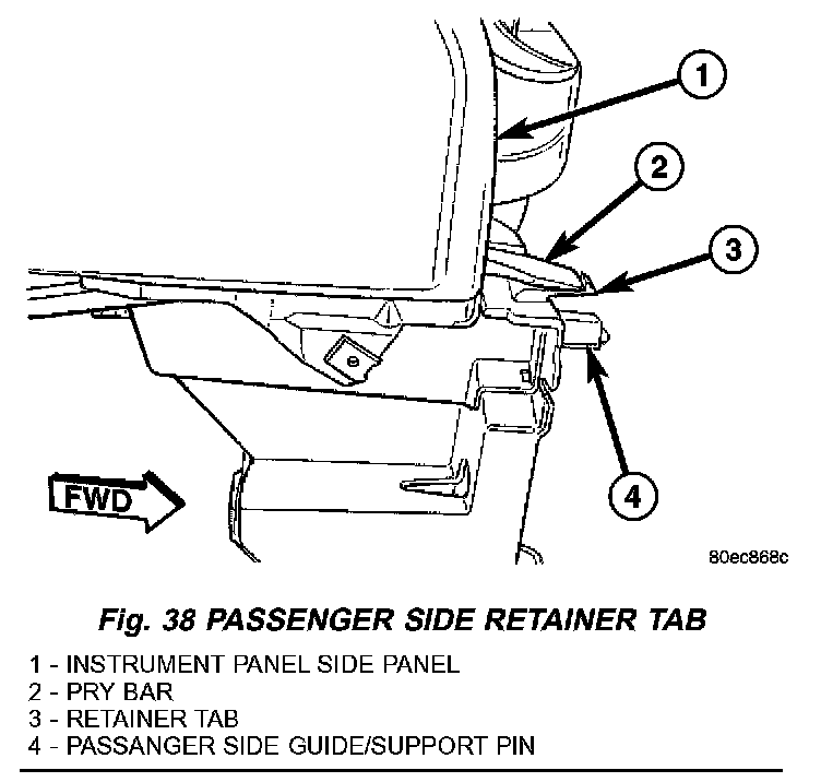
40. Depress the tab on the passenger side and with the aid of an assistant, lift the instrument panel assembly upward off of the studs on the dash panel near the windshield fence line and pull the instrument panel rearward from the dash panel and the cowl side inner panels and remove it through the driver side front door of the vehicle. (Fig. 38)
INSTALLATION
WARNING: ON VEHICLES EQUIPPED WITH AIR-BAGS, DISABLE THE AIRBAG SYSTEM BEFORE ATTEMPTING ANY STEERING WHEEL, STEERING COLUMN, OR INSTRUMENT PANEL COMPONENT DIAGNOSIS OR SERVICE. DISCONNECT AND ISOLATE THE BATTERY NEGATIVE (GROUND) CABLE, THEN WAIT TWO MINUTES FOR THE AIRBAG SYSTEM CAPACITOR TO DISCHARGE BEFORE PERFORMING FURTHER DIAGNOSIS OR SERVICE. THIS IS THE ONLY SURE WAY TO DISABLE THE AIRBAG SYSTEM. FAILURE TO TAKE THE PROPER PRECAUTIONS COULD RESULT IN ACCIDENTAL AIR-BAG DEPLOYMENT AND POSSIBLE PERSONAL INJURY.
1. Prior to installing the instrument panel into the vehicle, loosen the three nuts that secure the instrument panel intermediate bracket and the accel-erator pedal assembly to the studs on the dash panel (Fig. 30).
Fig. 23:
2. With the aid of an assistant, load the instrument panel assembly through the driver side front door of the vehicle and hang it on the studs on the dash panel near the windshield fence line (Fig. 23).
3. Be certain that the molded plastic guide/pin formations on the instrument panel structural duct are inserted into and seated in the guide holes at each cowl side inner panel.
4. Loosely install the two screws that secure each end of the instrument panel to the cowl side inner panels.
Fig. 36:
5. Install the two screws that secure the passenger side instrument panel structural duct to the heater and air conditioner housing (Fig. 36), and tighten to 11 N.m (8 ft. lbs.).
Fig. 29:
6. Install the one screw that secures the instrument panel steering column support bracket to the driver side end of the heater and air conditioner housing (Fig. 29), and tighten the to 11 N.m (8 ft. lbs.).
Fig. 33:
Fig. 37:
7. Tighten the two screws that secure each end of the instrument panel to the cowl side inner panels (Fig. 33) and (Fig. 37), to 11 N.m (8 ft. lbs.).
Fig. 30:
8. Install the one screw that secures the instrument panel steering column support bracket to the intermediate bracket on the driver side dash panel (Fig. 30), and tighten to 11 Nm (8 ft. lbs.).
9. Tighten the three nuts that secure the instrument panel intermediate bracket and the accelerator pedal assembly to the studs on the dash panel to 11 Nm (8 ft. lbs.).
10. Install the safety strap and tighten the nut.
11. Install the four nuts that secure the instrument panel to the studs on the dash panel near the windshield fence line and tighten to 11 N.m (8 ft. lbs.).
Fig. 31:
12. Install the nut that secures the instrument panel steering column support bracket to the stud on the driver side cowl plenum panel (Fig. 31), and tighten to 28 N.m (21 ft. lbs.).
13. Install the instrument panel to center floor tunnel bracket onto the instrument panel and the floor panel transmission tunnel.
Fig. 35:
14. Connect the two instrument panel wire harness connectors to the two heater and air conditioner housing connectors located near the blower motor on the passenger side end of the housing (Fig. 35).
15. Connect the two halves of the radio antenna coaxial cable connector near the passenger cowl side inner panel under the end of the instrument panel.
Fig. 34:
16. Connect the instrument panel wire harness connector to the lower cavity of the inline connector on the passenger side cowl side inner panel and tighten the connector screw (Fig. 34).
17. Install the lower right center bezel onto the instrument panel.
18. Install the end cap onto the instrument panel.
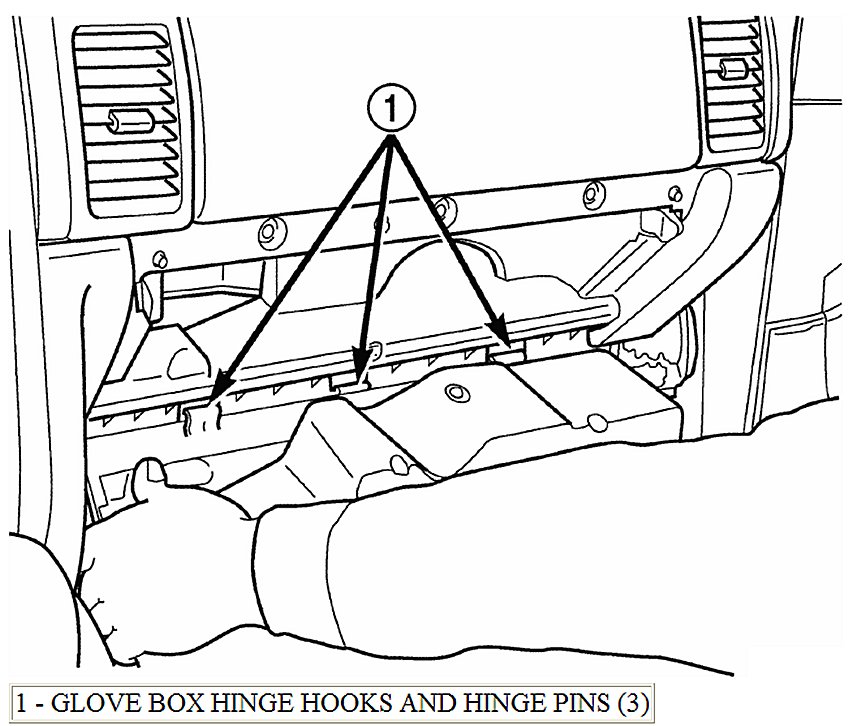
19. Install the glove box.
20. If equipped with the manual heating and air conditioning system, connect the vacuum harness connector located near the driver side of the floor panel transmission tunnel behind the driver side floor duct.
Fig. 29:
21. Position the driver side floor duct to the heater and air conditioner housing near the driver side of the floor panel transmission tunnel (Fig. 29).
22. Install the one screw that secures the driver side floor duct to the heater and air conditioner housing near the driver side of the floor panel transmission tunnel.
Fig. 28:
23. Route the instrument panel wire harness to the floor panel transmission tunnel and engage the retainers that secure the harness to the mounting brackets on the tunnel (Fig. 28).
24. Install the instrument panel wire harness ground eyelets to the studs on the floor panel transmission tunnel in front of and behind the airbag control module and secure the eyelets with nuts and tighten to 7 N.m (60 in. lbs.).
25. Connect the instrument panel wire harness connectors to the following floor panel transmission tunnel components: - the airbag control module (ACM) connector receptacle - the park brake switch terminal - the transmission shifter connector receptacle.
Fig. 27:
26. Connect the left and right body wire harness connectors, the ignition off draw (IOD) wire harness connector and the fused B(+) wire harness connector to the connector receptacles of the junction block (JB) and tighten the connector screws (Fig. 27).
27. Engage the lower steering column shaft with the steering shaft coupler and position the steering column to the mounting studs on the instrument panel steering column support bracket (Fig. 26).
28. Install the four nuts that secure the steering column to the studs on the instrument panel steering column support bracket and tighten to 11 N.m (8 ft. lbs.).
29. Install the bolt that secures the coupler to the lower steering column shaft and tighten to 49 N.m (36 ft. lbs.).
30. Turn the ignition switch to the On position, then install the shifter interlock cable connector into the ignition lock housing receptacle.
Fig. 25:
31. Connect the instrument panel wire harness connectors to the following steering column components (Fig. 25): - the two lower clockspring connector receptacles - the left multi-function switch connector receptacle - the right multi-function switch connector receptacle - the two ignition switch connector receptacles - the shifter interlock solenoid connector receptacle - if the vehicle is so equipped, the sentry key immobilizer module (SKIM) connector receptacle.
Fig. 24:
32. Position the lower tilting steering column shroud to the steering column multi-function switch mounting housing, then install and tighten the screw that secures the shroud to the housing (Fig. 24).
33. Position the upper tilting steering column shroud over the steering column. Align the upper and lower shrouds with each other and snap the two halves together.
34. Install the steering column bracket onto the instrument panel steering column support bracket. Steering Column Trim/Bracket Replacement
35. Install the steering column opening cover.
36. Install the cluster bezel. Instrument Panel Center Bezel
37. Install the fuse cover onto the JB.
38. Install the console onto the floor panel transmission tunnel. Instrument Panel to Center Floor Tunnel Bracket Replacement
39. Install the trim panels onto the right and left inner cowl sides.
40. Install the scuff plates onto the right and left front door sills.
41. Install the top cover. Instrument Panel Top Cover
42. Install the trim onto the right and left a-pillars.
43. Connect the battery negative cable.