DTC 21-9x
DTC 21-9x ("x" can be 0 thru 9 or A thru F) Short to Ground in Driver's Seat Belt TensionerSpecial Tools Required
- SRS inflator simulator 07SAZ-TB4011A
- SRS simulator lead C 07TAZ-SZ5011A
- SRS simulator lead F 07XAZ-SZ30100
1. Erase the DTC memory.
2. Turn the ignition switch ON (II), and check that the SRS indicator comes on for about 6 seconds and then goes off.
Does the SRS indicator stay on, and is DTC 21-9x indicated?
YES - Go to step 3.
NO - Intermittent failure, system is OK at this time. Go to Troubleshooting Intermittent Failures. Troubleshooting Intermittent Failures If another DTC is indicated, go to the DTC Troubleshooting Index. DTC List - Supplemental Restraint System
3. Turn the ignition switch OFF. Disconnect the negative cable from the battery, and wait for 3 minutes.
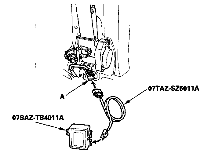
4. Disconnect the driver's seat belt tensioner 2P connector from the left side wire harness (A).
5. Connect the SRS inflator simulator (2 ohm connector) and simulator lead C to the left side wire harness.
6. Reconnect the negative cable to the battery.
7. Erase the DTC memory.
8. Check for a DTC.
Is DTC 2 1-9x indicated?
YES - Go to step 9.
NO - Short to ground in the driver's seat belt tensioner replace the driver's seat belt.
9. Turn the ignition switch OFF. Disconnect the negative cable from the battery, and wait for 3 minutes.
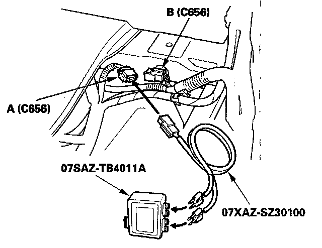
10. Disconnect SRS harness 4P connector C656 (A) from left side wire harness 4P connector C656 (B).
11. Connect the SRS inflator simulator (2 ohm connectors) and simulator lead F to the SRS harness.
12. Reconnect the negative cable to the battery.
13. Erase the DTC memory.
14. Check for a DTC.
Is DTC 21-9x indicated?
YES - Go to step 15.
NO - Short to ground in the left side wire harness replace the left side wire harness.
15. Turn the ignition switch OFF. Disconnect the negative cable from the battery, and wait for 3 minutes.
16. Disconnect the front passenger's seat belt tensioner connector.
17. Disconnect SRS unit connector B (28P) from the SRS unit.
18. Disconnect the simulator lead from the SRS harness 4P connector.
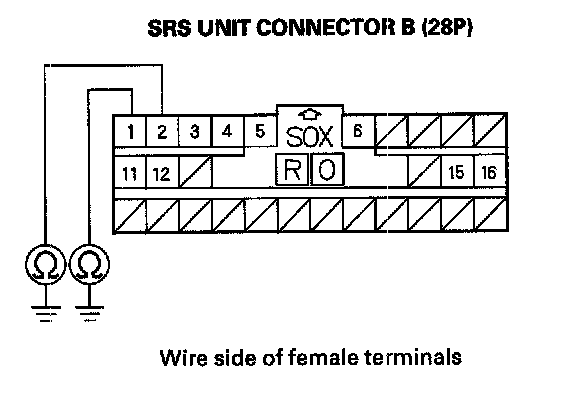
19. Check resistance between the No. 1 terminal of SRS unit connector B (28P) and body ground, and between the No. 2 terminal and body ground. There should be an open circuit or at least 1 M ohm.
Is the resistance as specified?
YES - Faulty SRS unit replace the SRS unit.
NO - Go to step 20.
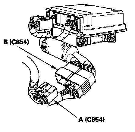
20. Disconnect SRS harness 28P connector C854 (A) from SRS subharness connector C854 (B).
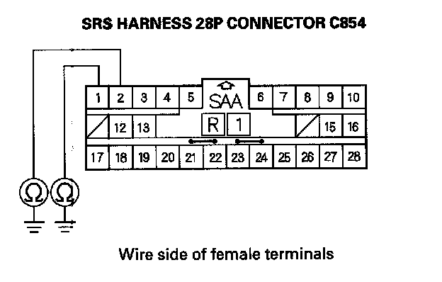
21. Check resistance between the No. 1 terminal of SRS harness 28P connector C854 and body ground, and between the No. 2 terminal and body ground. There should be an open circuit or at least 1 M ohm.
Is the resistance as specified?
YES - Short to ground in the SRS subharness replace the SRS subharness.
NO - Short to the ground in the SRS harness replace the SRS harness.