Pinpoint Test I: DTCs U300E:62, U300F:62, U3010:62 And U3011:62
Steering Column Switches
Pinpoint Test I: DTCs U300E:62, U300F:62, U3010:62 and U3011:62
Refer to Wiring Diagram Set 13, Power Distribution for schematic and connector information. Diagrams By Number
Refer to Wiring Diagram Set 20, Starting System for schematic and connector information. Diagrams By Number
Normal Operation
The Remote Function Actuator (RFA) module receives a direct input from the start/stop switch. After receiving this input, the RFA module activates the smart keyless entry ignition relay, the smart keyless entry accessory relay and the main ignition relay. The Instrument Panel Cluster (IPC) receives power from the 2 smart keyless entry relays and sends an ignition status message to the RFA module over the Controller Area Network (CAN), the RFA module uses this status message as a way to self-test.
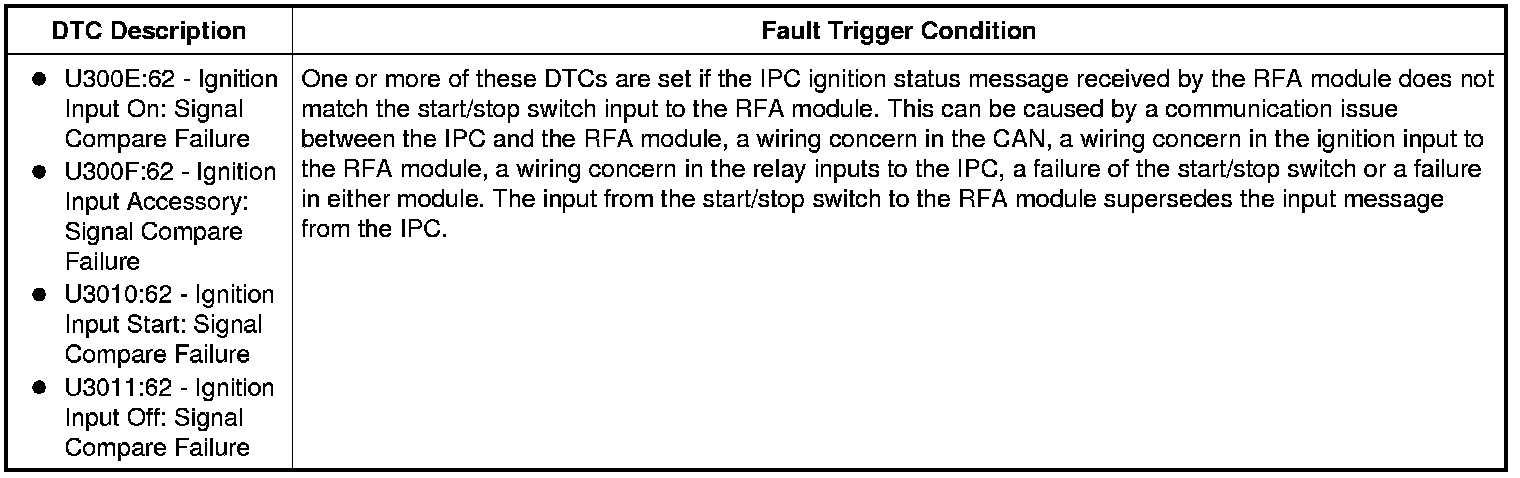
This pinpoint test is intended to diagnose the following:
- Fuses
- Wiring, terminals or connectors
- Smart keyless entry accessory relay
- Start/stop switch
- IPC
- RFA module
PINPOINT TEST I: DTCs U300E:62, U300F:62, U3010:62 AND U3011:62
NOTICE: Use the Flex Probe Kit for all test connections to prevent damage to the wiring terminals. Do not use standard multi-meter probes.
-------------------------------------------------
I1 CARRY OUT THE IPC SELF-TEST
- Ignition ON.
- Enter the following diagnostic mode on the scan tool: Self Test - IPC.
- Did the IPC communicate with the scan tool?
Yes
GO to I9.
No
GO to I2.
-------------------------------------------------
I2 CHECK THE IGNITION AND ACCESSORY INPUTS TO THE IPC
NOTE: Record the results for this pinpoint test step, they will be referred to later in this pinpoint test.
- Ignition OFF.
- Disconnect: IPC C220.
- Ignition ON.
- Measure the voltage between ground and:
- IPC C220-4, circuit CBP21 (BU/GY), harness side.
- IPC C220-15, circuit CBP19 (BN/WH), harness side.
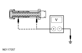
- Are the voltages greater than 10 volts?
Yes
REFER to Module Communications Network Testing and Inspection to diagnose no communication with the IPC.
No
If the voltage on both CBP21 (BU/GY) and CBP19 (BN/WH) are less than 10 volts, GO to I3. If only the voltage on CBP19 (BN/WH) is less than 10 volts, GO to I5. If only the voltage on CBP21 (BU/GY) is less than 10 volts, GO to I7.
-------------------------------------------------
I3 CHECK THE IPC SMART KEYLESS ENTRY IGNITION RELAY INPUT CIRCUIT FOR AN OPEN
- Ignition OFF.
- Disconnect: CJB Fuse 21 (10A).
- Measure the resistance between IPC C220-4, circuit CBP21 (BU/GY), harness side and CJB fuse 21 (10A), circuit CBP21 (BU/GY), output side.
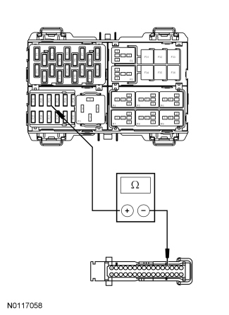
- Is the resistance less than 5 ohms?
Yes
VERIFY CJB fuse 21 (10A) is OK.
If OK, GO to I4.
If not OK, REFER to the Wiring Diagrams to identify the possible causes of the circuit short. Diagrams By Number
No
REPAIR circuit CBP21 (BU/GY). CLEAR the DTCs. REPEAT the self-test.
-------------------------------------------------
I4 CHECK THE SMART KEYLESS ENTRY IGNITION RELAY OUTPUT TO CJB FUSE 21 (10A)
- Disconnect: Smart Keyless Entry Ignition Relay.
- Measure the resistance between smart keyless entry ignition relay cavity 5, circuit CDC32 (BN/YE), and CJB fuse 21 (10A), circuit CDC32 (BN/YE), input side.
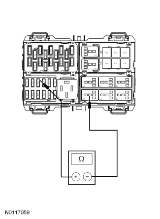
- Is the resistance less than 5 ohms?
Yes
If the voltage measured on CBP19 (BN/WH) in Step I2 was also less than 10 volts, GO to I5. If the voltage measured on CBP19 (BN/WH) in Step I2 was greater than 10 volts, GO to I10.
No
REPAIR circuit CDC32 (BN/YE). CLEAR the DTCs. REPEAT the self-test.
-------------------------------------------------
I5 CHECK THE IPC SMART KEYLESS ENTRY ACCESSORY RELAY INPUT CIRCUIT FOR AN OPEN
- Ignition OFF.
- Disconnect: CJB Fuse 19 (7.5A).
- Measure the resistance between IPC C220-15, circuit CBP19 (BN/WH), harness side and CJB fuse 19 (7.5A), circuit CBP19 (BN/WH), output side.
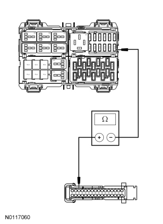
- Is the resistance less than 5 ohms?
Yes
VERIFY CJB fuse 19 (7.5A) is OK.
If OK, GO to I6.
If not OK, REFER to the Wiring Diagrams to identify the possible causes of the circuit short. Diagrams By Number
No
REPAIR circuit CBP19 (BN/WH). CLEAR the DTCs. REPEAT the self-test.
-------------------------------------------------
I6 CHECK THE SMART KEYLESS ENTRY ACCESSORY RELAY OUTPUT TO CJB FUSE 19 (7.5A)
- Disconnect: Smart Keyless Entry Accessory Relay.
- Measure the resistance between smart keyless entry accessory relay cavity 5, circuit CDC33 (VT/GN), and CJB fuse 19 (7.5A), circuit CDC33 (VT/GN), input side.
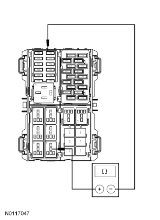
- Is the resistance less than 5 ohms?
Yes
GO to I7.
No
REPAIR circuit CDC33 (VT/GN). CLEAR the DTCs. REPEAT the self-test.
-------------------------------------------------
I7 CHECK THE SMART KEYLESS ENTRY ACCESSORY RELAY GROUND CIRCUIT FOR AN OPEN
- Measure the resistance between smart keyless entry accessory relay cavity 2, circuit GD145 (BK/BU), and ground.
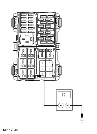
- Is the resistance less than 5 ohms?
Yes
GO to I8.
No
REPAIR circuit GD145 (BK/BU). CLEAR the DTCs. REPEAT the self-test.
-------------------------------------------------
I8 ISOLATE THE SMART KEYLESS ENTRY ACCESSORY RELAY
- Carry out the appropriate relay component test.
Refer to Power Distribution Relay for component testing.
- Is the relay OK?
Yes
GO to I10.
No
INSTALL a new smart keyless entry accessory relay. CLEAR the DTCs. TEST the system for normal operation.
-------------------------------------------------
I9 ACT ON IPC DTCs
- Refer to the results of the IPC self-test.
- Were any IPC DTCs present?
Yes
REFER to the Instrument Panel Cluster (IPC) DTC Chart in Instrumentation, Message Center, and Warning Chimes Testing and Inspection.
No
GO to I10.
-------------------------------------------------
I10 REVIEW THE RFA MODULE DTCs
- Review the RFA module DTCs retrieved during Inspection and Verification.
- Are any DTCs other than U300E:62, U300F:62, U3010:62 and/or U3011:62 present?
Yes
DIAGNOSE all other RFA module DTCs before diagnosing U300E:62, U300F:62, U3010:62 and U3011:62. For DTCs B108B:23, B108B:29 and B108C:23, GO to Pinpoint Test E. For DTCs B10E7:11, B10E7:12, B10E7:16 and B10E7:17, GO to Pinpoint Test F. For DTCs U3004:11 and U3004:12, GO to Pinpoint Test G. For all other RFA module DTCs, REFER to the Remote Function Actuator (RFA) Module DTC Chart. Pinpoint Test E: DTCs B108B:23, 29 And B108C:23 Pinpoint Test F: DTCs B10E7:11, 12, 16 And 17 Pinpoint Test G: DTCs U3004:11 And 12 [1][2]Diagnostic Trouble Code Descriptions
No
For DTCs U300E:62, U300F:62 and/or U3011:62, GO to I11. For DTC U3010:62, GO to I12.
-------------------------------------------------
I11 CHECK THE STARTER MOTOR CONTROL SENSE CIRCUIT FOR A SHORT TO VOLTAGE
- Ignition OFF.
- Disconnect: RFA Module C3503C.
- Disconnect: IPC C220.
- Disconnect: Starter Inhibit Relay.
- Ignition ON.
- Measure the voltage between starter inhibit relay, cavity 1, circuit CDC54 (WH/GN), harness side and ground.
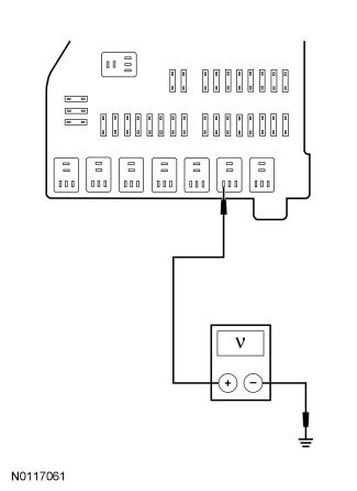
- Is any voltage present?
Yes
REPAIR circuit CDC54 (WH/GN). CLEAR the DTCs. REPEAT the self-test.
No
GO to I12.
-------------------------------------------------
I12 CHECK THE IPC ACCESSORY INPUT CIRCUIT FOR A SHORT TO VOLTAGE
- Ignition OFF.
- Disconnect: IPC C220 (if not previously disconnected).
- Connect: CJB Fuse 19 (7.5A) (if previously disconnected).
- Connect: Smart Keyless Entry Accessory Relay (if previously disconnected).
- Ignition ON.
- Measure the voltage between IPC C220-15, circuit CBP19 (BN/WH), harness side and ground.
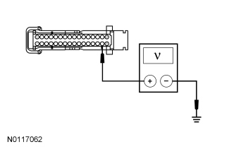
- Is any voltage present?
Yes
GO to I13.
No
GO to I14.
-------------------------------------------------
I13 ISOLATE THE SMART KEYLESS ENTRY ACCESSORY RELAY AND CHECK THE IPC ACCESSORY INPUT CIRCUIT FOR A SHORT TO VOLTAGE
- Disconnect: Smart Keyless Entry Accessory Relay.
- Measure the voltage between IPC C220-15, circuit CBP19 (BN/WH), harness side and ground.
- Is any voltage present?
Yes
REPAIR circuit CBP19 (BN/WH). CLEAR the DTCs. REPEAT the self-test.
No
INSTALL a new smart keyless entry accessory relay. CLEAR the DTCs. REPEAT the self-test.
-------------------------------------------------
I14 CHECK THE STARTER MOTOR CONTROL SENSE CIRCUIT FOR AN OPEN CIRCUIT
- Ignition OFF.
- Measure the resistance between starter inhibit relay cavity 1, circuit CDC54 (WH/GN), and RFA module C3503C-6, circuit CDC54 (WH/GN), harness side.
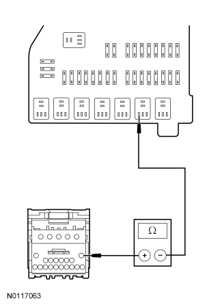
- Is the resistance less than 5 ohms?
Yes
GO to I15.
No
REPAIR circuit CDC54 (WH/GN). CLEAR the DTCs. REPEAT the self-test.
-------------------------------------------------
I15 CHECK THE STARTER MOTOR CONTROL SENSE CIRCUIT FOR A SHORT TO GROUND
- Measure the resistance between starter inhibit relay cavity 1, circuit CDC54 (WH/GN), and ground.
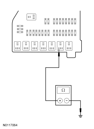
- Is the resistance greater than 10,000 ohms?
Yes
GO to I16.
No
REPAIR circuit CDC54 (WH/GN). CLEAR the DTCs. REPEAT the self-test.
-------------------------------------------------
I16 CHECK FOR CORRECT RFA MODULE OPERATION
- Disconnect all RFA module electrical connectors.
- Check connectors for:
- corrosion
- pushed-out pins
- bent pins
- spread terminals
- Connect all RFA module electrical connectors and make sure they are seated correctly.
- Connect all other disconnected module connectors, relays and/or fuses.
- Operate the system and verify the concern is still present.
- Is the concern still present?
Yes
INSTALL a new RFA module. REFER to Multifunction Electronic Modules Service and Repair.
CONFIGURE the new RFA module. REFER to Programmable Module Installation (PMI) in Module Configuration Programmable Module Installation (PMI).
CARRY OUT a Passive Anti-Theft System (PATS) Parameter Reset. REFER to Passive Anti-Theft System (PATS) Parameter Reset-Intelligent Access (IA) in Anti-Theft - Passive Anti-Theft System (PATS) Passive Anti-Theft System (PATS) Parameter Reset.
PROGRAM 2 Intelligent Access (IA) keys. REFER to Key Programming Using Diagnostic Equipment-Intelligent Access (IA) in Anti-Theft - Passive Anti-Theft System (PATS) Key Programming.
TEST the system for normal operation.
No
The system is operating correctly at this time. The concern may have been caused by a loose or corroded connector. TEST the system for normal operation.
-------------------------------------------------