Pinpoint Test O: The Vehicle Does Not Shift Between 4A (4X4 AUTO) and 4H (4X4) Modes Correctly
Four Wheel Drive (4WD) Systems - 2-Speed Torque-On-Demand
Pinpoint Test O: The Vehicle Does Not Shift Between 4A (4X4 AUTO) and 4H (4X4) Modes Correctly
Refer to Wiring Diagram Set 34, Four-Wheel Drive System for schematic and connector information Electrical Diagrams.
Normal Operation
In 2H mode, the Transfer Case Control Module (TCCM) supplies a ground path to the Integrated Wheel End (IWE) solenoid to apply vacuum to the IWEs (Integrated Wheel Ends) (disengaging the front hubs from the front axle). In AUTO, 4H and 4L modes, the TCCM (Transfer Case Control Module) does not supply the ground path to the IWE (Integrated Wheel End) solenoid, vacuum is not applied to the IWEs (Integrated Wheel Ends) and an internal spring keeps the hubs engaged. Systematically check the necessary inputs and outputs at the TCCM (Transfer Case Control Module), internal components of the transfer case, Mode Select Switch (MSS), IWE (Integrated Wheel End) components and drive axles.
This pinpoint test is intended to diagnose the following:
- MSS (Mode Select Switch)
- IWE (Integrated Wheel End)
- IWE (Integrated Wheel End) solenoid
- Transfer case
- Vacuum leaks
- Front axle assembly
- TCCM (Transfer Case Control Module)
- Wiring, terminals or connectors
PINPOINT TEST O : THE VEHICLE DOES NOT SHIFT BETWEEN 4A (4X4 AUTO) AND 4H (4X4) MODES CORRECTLY
O1 CHECK FOR TCCM (Transfer Case Control Module) DTCs
- Ignition ON.
- Enter the following diagnostic mode on the scan tool: Self-Test- TCCM (Transfer Case Control Module).
Are DTCs retrieved?
Yes
REFER to the TCCM (Transfer Case Control Module) DTC Chart for diagnosis. Four Wheel Drive (4WD) Systems - 2-Speed Torque-on-Demand
No
GO to O2.
O2 CHECK THE 4H INDICATOR
- Select 4H mode and observe the Instrument Cluster (IC).
Does the IC (Instrument Cluster) indicator lamp indicate 4H (4X4) mode?
Yes
GO to O8.
No
GO to O3.
O3 CHECK THE TCCM (Transfer Case Control Module) IGNITION POSITION (KEY_POS_4X4) PID
- Enter the following diagnostic mode on the scan tool: DataLogger- TCCM (Transfer Case Control Module).
- Monitor the KEY_POS_4X4 PID while cycling through each position.
Does the ignition position PID match the ignition switch positions?
Yes
GO to O4.
No
REFER to Steering Column to diagnose the ignition switch concern.
O4 CHECK THE TCCM (Transfer Case Control Module) 4WD SWITCH STATUS (4X4_SW) PID
- Monitor 4X4_SW PID while cycling the MSS (Mode Select Switch) through each position.
MSS (Mode Select Switch) Position PID Status 2H 2WD 4A Automatic 4H 4WD-HIGH 4L 4WD-LOW
Does each PID status agree with each MSS (Mode Select Switch) position?
Yes
GO to O7.
No
GO to O5.
O5 CHECK THE MSS (Mode Select Switch) RESISTANCE VALUES
- Ignition OFF.
- Disconnect: MSS (Mode Select Switch) C284.
- Measure the resistance between MSS (Mode Select Switch) C284 pin 2 and pin 3, component side. Refer to the following chart:
MSS (Mode Select Switch) Position Resistance (±1%) 2H 619 ohms 4A 270 ohms 4H 130 ohms 4L 62 ohms
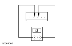
Are the resistance values within specification?
Yes
GO to O6.
No
INSTALL a new MSS (Mode Select Switch). CLEAR the DTCs. TEST the system for normal operation.
O6 CHECK THE MSS (Mode Select Switch) CONTROL AND RETURN CIRCUITS FOR AN OPEN
- Disconnect: TCCM (Transfer Case Control Module) C2371A.
- Measure the resistance between TCCM (Transfer Case Control Module) C2371A-16, circuit CCF13 (WH/BU), harness side and MSS (Mode Select Switch) C2071-3, circuit CCF13 (WH/BU), harness side.
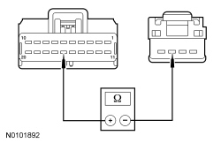
- Measure the resistance between TCCM (Transfer Case Control Module) C2371A-14, circuit RCF13 (WH/BN), harness side and MSS (Mode Select Switch) C2071-2, circuit RCF13 (WH/BN), harness side.
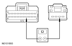
Are the resistances less than 3 ohms?
Yes
GO to O19.
No
REPAIR the affected circuit(s). CLEAR the DTCs. TEST the system for normal operation.
O7 CHECK THE 4WD (Four-Wheel Drive) PWM (Pulse-Width Modulation) CLUTCH STATUS (4WD_CLTCH_OUT) PID
- Switch the MSS (Mode Select Switch) to 4H mode.
- Monitor the 4WD_CLTCH_OUT PID.
Does the 4WD_CLTCH_OUT PID indicate 2 to 10% clutch application at closed throttle?
Yes
GO to O19.
No
DIAGNOSE the PCM. REFER to Computers and Control Systems Information and the HS-CAN. REFER to Information Bus. CLEAR the DTCs. TEST the system for normal operation.
O8 CHECK FOR WIND-UP IN 4H MODE
- Switch the MSS (Mode Select Switch) to 4H mode.
- Drive the vehicle on a dry, hard surface in turns while applying the throttle.
Is wind-up present in turns?
Yes
GO to O13.
No
GO to O9.
O9 CHECK THE 4WD (Four-Wheel Drive) PWM (Pulse-Width Modulation) CLUTCH STATUS (4WD_CLTCH_OUT) PID AT WOT (Wide Open Throttle)
- Enter the following diagnostic mode on the scan tool: DataLogger- TCCM (Transfer Case Control Module).
- Monitor the 4WD_CLTCH_OUT PID at Wide Open Throttle (WOT), Key ON Engine OFF (KOEO).
Does the 4WD_CLTCH_OUT PID read 98% at WOT (Wide Open Throttle)?
Yes
GO to O11.
No
GO to O10.
O10 CHECK THE ABSOLUTE THROTTLE POSITION (TP_TCCM) PID
- NOTE: The TP_TCCM PID is Accelerator Pedal Position (APP) as communicated by the PCM via HS-CAN (High Speed Controller Area Network).
Slowly move the accelerator pedal from closed throttle to WOT (Wide Open Throttle) and observe the TP_TCCM PID.
Does the TP_TCCM PID vary between 0% at closed throttle and 100% at WOT (Wide Open Throttle)?
Yes
GO to O11.
No
DIAGNOSE the PCM. REFER to Computers and Control Systems Information and the HS-CAN (High Speed Controller Area Network). REFER to Information Bus.
O11 CHECK FOR TRANSFER CASE CLUTCH ENGAGEMENT WITH THE 4WD (Four-Wheel Drive) PWM (Pulse-Width Modulation) CLUTCH STATUS (4WD_CLTCH_OUT) ACTIVE COMMAND AND 4WD (Four-Wheel Drive) PWM (Pulse-Width Modulation) CLUTCH STATUS (4WD_CLTCH_OUT) PID
- Using the 4WD_CLTCH_OUT active command, engage the transfer case clutch to 100% while monitoring the 4WD_CLTCH_OUT PID.
Does the PID read 100%?
Yes
END the active command. CHECK the transfer case.
No
END the active command. GO to O12.
O12 CHECK THE IC (Instrument Cluster) INDICATOR IN AUTO MODE
- Select 4A mode and observe the IC (Instrument Cluster).
Does the IC (Instrument Cluster) message center indicate 4A (4X4 AUTO) mode?
Yes
GO to O13.
No
GO to Pinpoint Test V. Pinpoint Test V: The 4X4 Mode Indicators Do Not Operate Correctly/Do Not Operate
O13 CHECK FOR WIND-UP IN AUTO MODE
- Drive the vehicle on a dry, hard surface in turns while applying the throttle.
Is wind-up present in turns?
Yes
GO to O14.
No
The system is operating correctly.
O14 CHECK THE 4WD (Four-Wheel Drive) PWM (Pulse-Width Modulation) CLUTCH STATUS (4WD_CLTCH_OUT) PID
- Monitor the 4WD_CLTCH_OUT PID at closed throttle, KOEO (Key ON Engine OFF).
Does the 4WD_CLTCH_OUT PID indicate 2 to 10% clutch application at closed throttle?
Yes
GO to O15.
No
GO to O17.
O15 CHECK VOLTAGE ON THE CLUTCH CONTROL CIRCUIT USING THE 4WD (Four-Wheel Drive) PWM (Pulse-Width Modulation) CLUTCH STATUS (4WD_CLTCH_OUT) ACTIVE COMMAND
- Using the 4WD_CLTCH_OUT active command, command the transfer case clutch to 4%.
- Measure the voltage by carefully back-probing transfer case C350-16, circuit CCF03 (GY/BN), component side and the transfer case housing.
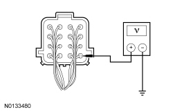
Is the voltage approximately 0.2 to 0.4 volt?
Yes
END the active command. CHECK the transfer case.
No
GO to O16.
O16 CHECK CLUTCH CONTROL CIRCUIT FOR AN OPEN
- Ignition OFF.
- Disconnect: Transfer Case C350.
- Disconnect: TCCM (Transfer Case Control Module) C2371B.
- Measure the resistance between transfer case C350-16, circuit CCF03 (GY/BN), harness side and TCCM (Transfer Case Control Module) C2371B-1, circuit CCF03 (GY/BN), harness side.
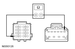
Is the resistance less than 3 ohms?
Yes
GO to O17.
No
REPAIR circuit CCF03 (GY/BN). CLEAR the DTCs. TEST the system for normal operation.
O17 CHECK THE ABS MODULE WHEEL SPEED SENSOR PIDs
- Enter the following diagnostic mode on the scan tool: DataLogger- ABS Module.
- While driving the vehicle at 30 km/h (18 mph), monitor the following wheel speed sensor PIDs:
- Left Front Wheel Speed Sensor (LF_WSPD)
- Left Rear Wheel Speed Sensor (LR_WSPD)
- Right Front Wheel Speed Sensor (RF_WSPD)
- Right Rear Wheel Speed Sensor (RR_WSPD)
- Compare the speedometer reading to the wheel speed sensor PIDs.
Do the wheel speed sensor PIDs and speedometer speeds match within 1.5 km/h (1 mph)?
Yes
GO to O18.
No
CHECK the ABS.
O18 CHECK THE ABSOLUTE THROTTLE POSITION (TP_TCCM) PID
- Enter the following diagnostic mode on the scan tool: DataLogger- TCCM (Transfer Case Control Module).
- Ignition ON.
- Monitor the TP_TCCM PID.
- NOTE: The TP_TCCM PID is Accelerator Pedal Position (APP) as communicated by the PCM via High Speed Controller Area Network (HS-CAN).
Slowly move throttle from closed throttle to Wide Open Throttle (WOT) and observe the TP_TCCM PID.
Does the TP_TCCM PID vary between 0% at closed throttle and 100% at WOT (Wide Open Throttle)?
Yes
GO to O19.
No
DIAGNOSE the PCM. REFER to Computers and Control Systems Information and the HS-CAN (High Speed Controller Area Network). REFER to Information Bus.
O19 CHECK FOR CORRECT TCCM (Transfer Case Control Module) OPERATION
- Ignition OFF.
- Disconnect all TCCM (Transfer Case Control Module) connectors.
- Check for:
- corrosion
- damaged pins
- pushed-out pins
- Connect all TCCM (Transfer Case Control Module) connectors and make sure they are seated correctly.
- Operate the system and verify the concern is still present.
Is the concern still present?
Yes
INSTALL a new TCCM (Transfer Case Control Module). REFER to 4X4 Control Module . CLEAR the DTCs. TEST the system for normal operation.
No
The system is operating correctly at this time. Concern may have been caused by a loose or corroded connector. ADDRESS the root cause of the connector concern. TEST the system for normal operation.