Pinpoint Test C: No Power in RUN
Steering Column Switches
Pinpoint Test C: No Power in RUN
Refer to Wiring Diagram Set 13, Power Distribution/SJB for schematic and connector information Electrical Diagrams.
Normal Operation
When the ignition switch is placed in the RUN position, fused ignition voltage is sent to the Battery Junction Box (BJB) and the Smart Junction Box (SJB) through the following circuits:
- CDC33 (VT/GN)
- CDC32 (BN/YE)
- CDC34 (WH/OG)
This pinpoint test is intended to diagnose the following:
- Wiring, terminals or connectors
- Ignition switch
- SJB (Smart Junction Box)
PINPOINT TEST C : NO POWER IN RUN
NOTICE: Use the Flex Probe Kit for all test connections to prevent damage to the wiring terminals. Do not use standard multi-meter probes.
C1 CHECK THE IGNITION SWITCH
- Ignition OFF.
- Disconnect: Ignition Switch C250.
- Carry out the Ignition Switch Component Test.
Is the ignition switch OK?
Yes
GO to C2.
No
INSTALL a new ignition switch. REFER to Ignition Switch . TEST the system for normal operation.
C2 CHECK FOR VOLTAGE AT THE SJB (Smart Junction Box)
- Connect: Ignition Switch C250.
- Disconnect: SJB (Smart Junction Box) Fuse 43 (10A).
- Disconnect: SJB (Smart Junction Box) Fuse 44 (10A).
- Disconnect: SJB (Smart Junction Box) C2280B.
- Ignition ON.
- Measure the voltage between ground and:
- SJB (Smart Junction Box) fuse 43 (10A), circuit CDC33 (VT/GN), input side.
- SJB (Smart Junction Box) fuse 44 (10A), circuit CDC32 (BN/YE), input side.
- SJB (Smart Junction Box) C2280B-45, circuit CDC34 (WH/OG), harness side.
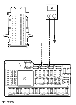
Are the voltages greater than 10 volts?
Yes
GO to C3.
No
REPAIR the affected circuit(s). TEST the system for normal operation.
C3 CHECK FOR VOLTAGE AT THE RUN/START RELAY
- Ignition OFF.
- Disconnect: Run/Start Relay.
- Ignition ON.
- Measure the voltage between run/start relay pin 1, circuit CDC34 (WH/OG), harness side and ground.
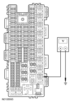
Is the voltage greater than 10 volts?
Yes
GO to C4.
No
REPAIR circuit CDC34 (WH/OG). TEST the system for normal operation.
C4 CHECK THE SJB (Smart Junction Box) CONNECTORS
- Check SJB (Smart Junction Box) connectors C2280A and C2280B for:
- corrosion.
- pushed-out pins.
- spread terminal.
- Connect: SJB (Smart Junction Box) C2280A.
- Connect: SJB (Smart Junction Box) C2280B.
- Make sure the connectors are seated correctly, then operate the system and verify the concern is still present.
Is the concern still present?
Yes
INSTALL a new SJB (Smart Junction Box). TEST the system for normal operation.
No
The system is operating correctly at this time. Concern may have been caused by a loose or corroded connector.