Pinpoint Test L: The Turn Signal Lamps Are Inoperative
Turn Signal and Hazard Lamps
Pinpoint Test L: The Turn Signal Lamps Are Inoperative
Refer to Wiring Diagram Set 90, Turn Signal/Stop/Hazard Lamps for schematic and connector information Electrical Diagrams.
Normal Operation
The Smart Junction Box (SJB) sends reference signals to the multifunction switch through the LH and RH turn signal request input circuits. When the multifunction switch is placed in the LH or RH TURN position, the voltage signal is routed to ground. When the SJB (Smart Junction Box) detects the multifunction switch in the LH or RH TURN position, the SJB (Smart Junction Box) provides voltage to the appropriate turn lamps.
This pinpoint test is intended to diagnose the following:
- Wiring, terminals or connectors
- Multifunction switch
- SJB (Smart Junction Box)
PINPOINT TEST L : THE TURN SIGNAL LAMPS ARE INOPERATIVE
NOTICE: Use the correct probe adapter(s) when making measurements. Failure to use the correct probe adapter(s) may damage the connector.
L1 CHECK FOR CORRECT HIGH BEAM OPERATION
- Place the headlamp switch in the HEADLAMPS ON position.
- Place the multifunction switch in the HIGH BEAM position while observing the high beam headlamps.
Do the high beams operate correctly?
Yes
PLACE the headlamp switch in the OFF position. GO to L2.
No
REFER to Headlamps Special Tool(s) Used With Diagnostics.
L2 CHECK FOR CORRECT STOPLAMP OPERATION
- Apply and release the brake pedal.
Do the stoplamps operate correctly?
Yes
GO to L3.
No
REFER to Stoplamps Special Tool(s) Used With Diagnostics.
L3 BYPASS THE MULTIFUNCTION SWITCH
- Ignition OFF.
- Disconnect: Multifunction Switch C202.
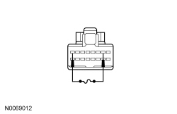
- For an inoperative LH turn signal, connect a fused jumper wire between the multifunction switch C202-2, circuit CLS20 (BN/BU), harness side and the multifunction switch C202-8, circuit GD138 (BK/WH), harness side.
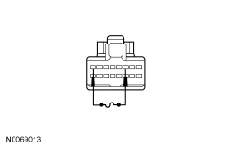
- For an inoperative RH turn signal, connect a fused jumper wire between the multifunction switch C202-3, circuit CLS24 (BN/WH), harness side and the multifunction switch C202-3, circuit GD138 (BK/WH), harness side.
- Ignition ON.
Do the turn signals in question flash on and off?
Yes
REMOVE the jumper wire. INSTALL a new multifunction switch. TEST the system for normal operation.
No
REMOVE the jumper wire. GO to L4.
L4 CHECK THE TURN SIGNAL REQUEST INPUT CIRCUIT FOR AN OPEN
- Disconnect: SJB (Smart Junction Box) C2280B.
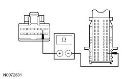
- For an inoperative LH turn signal, measure the resistance between the multifunction switch C202-2, circuit CLS20 (BN/BU), harness side and the SJB (Smart Junction Box) C2280B-42, circuit CLS20 (BN/BU), harness side.
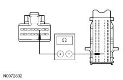
- For an inoperative RH turn signal, measure the resistance between the multifunction switch C202-3, circuit CLS24 (BN/WH), harness side and the SJB (Smart Junction Box) C2280B-29, circuit CLS24 (BN/WH), harness side.
Is the resistance less than 5 ohms?
Yes
GO to L5.
No
REPAIR circuit CLS20 (BN/BU) (LH turn signal) or circuit CLS24 (BN/WH) (RH turn signal) for an open. TEST the system for normal operation.
L5 CHECK FOR CORRECT SJB (Smart Junction Box) OPERATION
- Disconnect all the SJB (Smart Junction Box) connectors.
- Check for:
- corrosion
- damaged pins
- pushed-out pins
- Connect all the SJB (Smart Junction Box) connectors and make sure they seat correctly.
- Operate the system and verify the concern is still present.
Is the concern still present?
Yes
INSTALL a new SJB (Smart Junction Box). TEST the system for normal operation.
No
The system is operating correctly at this time. The concern may have been caused by a loose or corroded connector.