Pinpoint Test E: DTCs C1141, C1142, C1143, C1144, C1233, C1234, C1235 and C1236
Anti-Lock Control
Pinpoint Tests
Pinpoint Test E: DTCs C1141, C1142, C1143, C1144, C1233, C1234, C1235 and C1236
Refer to Wiring Diagram Set 42, Vehicle Dynamic Systems for schematic and connector information. Diagrams By Number
Normal Operation
The wheel speed sensors generate a square-wave signal that is sent to the ABS module that is proportional to wheel speed. The ABS module compares the wheel speed inputs from all wheel speed sensors to determine an impending lockup.
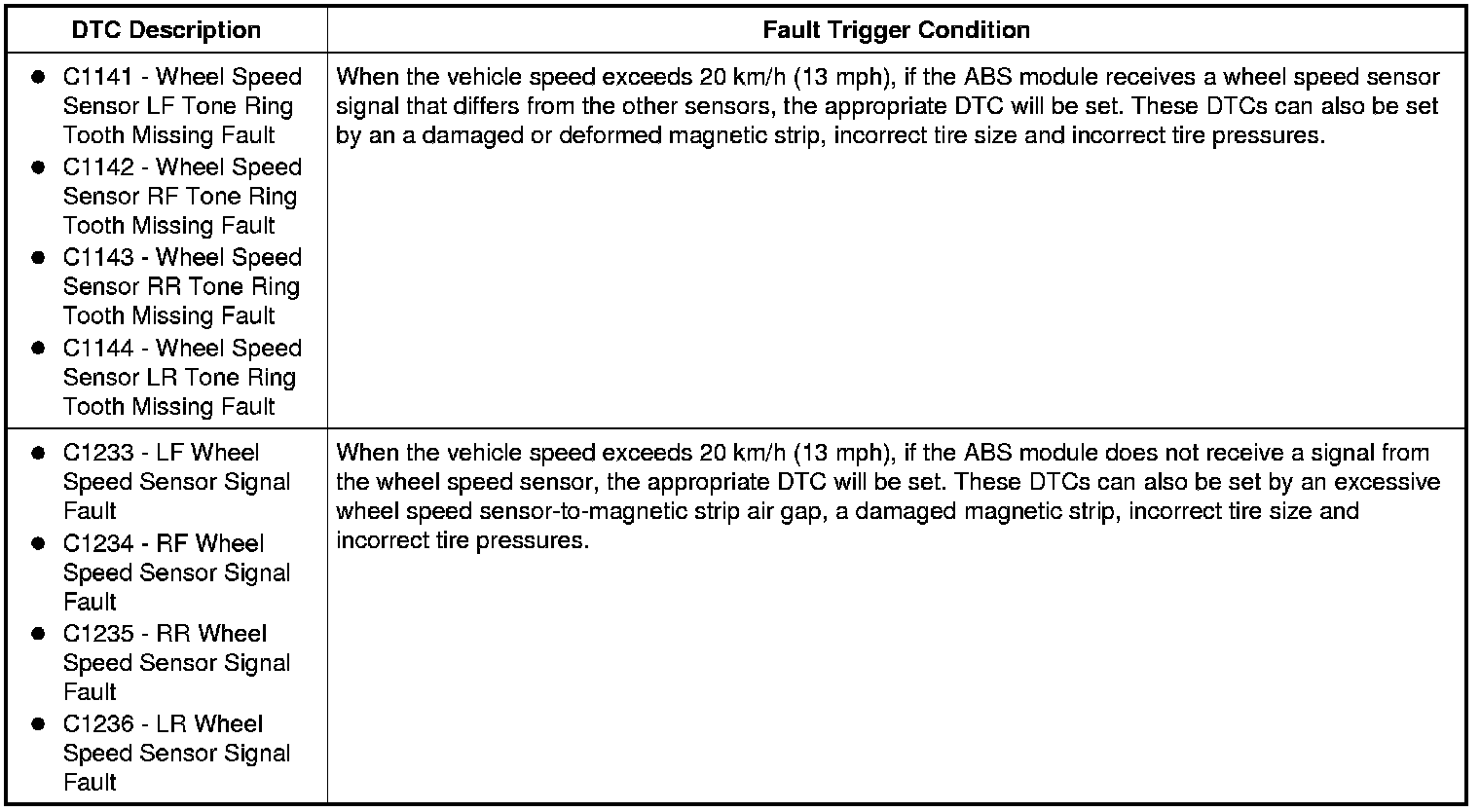
This pinpoint test is intended to diagnose the following:
- Wiring, terminals or connectors
- Wheel bearings
- Wheel speed sensor magnetic strip
- Wheel speed sensor
- ABS module
PINPOINT TEST E: DTCs C1141, C1142, C1143, C1144, C1233, C1234, C1235 AND C1236
NOTICE: Use the Flex Probe Kit for all test connections to prevent damage to the wiring terminals. Do not use standard multi-meter probes.
-------------------------------------------------
E1 CHECK THE DTCs FROM THE SELF-TEST
- Review the DTCs retrieved during Inspection and Verification.
- Was DTC C1145, C1155, C1165 or C1175 retrieved?
Yes
GO to Pinpoint Test D. Pinpoint Test D: DTCs C1145, C1155, C1165 and C1175
No
GO to E2.
-------------------------------------------------
E2 CHECK THE TIRES SIZE AND PRESSURE
- Verify that the tires are the correct size for the vehicle as indicated on the Vehicle Certification (VC) label.
- Verify that the air pressure in all the tires is correct as indicated on the VC label.
- Are the wheels and tires OK?
Yes
GO to E3.
No
INSTALL the correct tires or ADJUST tire pressure as necessary. CLEAR the DTCs. TEST the system for normal operation.
-------------------------------------------------
E3 INSPECT THE WHEEL SPEED SENSOR MOUNTING
- With the vehicle in NEUTRAL, position it on a hoist. Refer to Jacking and Lifting Service and Repair.
- Inspect the suspect wheel speed sensor for looseness.
- Is the wheel speed sensor loose?
Yes
TIGHTEN the wheel speed sensor to specification. REFER to Specifications. CLEAR the DTCs. GO to E4.
No
GO to E5.
-------------------------------------------------
E4 CHECK THE WHEEL SPEED PIDs
- Connect the scan tool.
- Ignition ON.
- Enter the following diagnostic mode on the scan tool: DataLogger - ABS Module.
- Monitor the following PIDs while driving the vehicle at a constant speed:
- Left Front Wheel Speed Sensor (LF_WSPD)
- Right Front Wheel Speed Sensor (RF_WSPD)
- Left Rear Wheel Speed Sensor (LR_WSPD)
- Right Rear Wheel Speed Sensor (RR_WSPD)
- Are all the wheel speed sensor PID values similar?
Yes
The vehicle is OK. The concern may have been caused by a loose wheel speed sensor.
No
GO to E5.
-------------------------------------------------
E5 INSPECT THE WHEEL SPEED SENSOR FOR DAMAGE
- NOTE: Examine the wheel speed sensor wire carefully with a good light source. Failure to verify damage in the wheel speed sensor wire can lead to unnecessary installation of a new component.
- Inspect the suspect wheel speed sensor for general damage.
- Is the wheel speed sensor OK?
Yes
GO to E6.
No
INSTALL a new wheel speed sensor. REFER to Wheel Speed Sensor - Front Wheel Speed Sensor - Front or Wheel Speed Sensor - Rear Wheel Speed Sensor - Rear. CLEAR the DTCs. REPEAT the self-test.
-------------------------------------------------
E6 INSPECT THE WHEEL SPEED SENSOR MAGNETIC STRIP AND WHEEL BEARING FOR DAMAGE
- Inspect the wheel bearing for damage.
- Inspect the suspect wheel bearing for dirt or other debris. Verify that the bearing is correctly installed and not deformed.
- Is the wheel bearing OK?
Yes
If the Active Wheel Speed Sensor Tester is available, GO to E7. If the Active Wheel Speed Sensor Tester is not available, GO to E9.
No
INSTALL a new front or rear wheel bearing. REFER to Front Suspension Front Suspension for front wheel bearings or Rear Suspension Rear Suspension for rear wheel bearings. CLEAR the DTCs. REPEAT the self-test.
-------------------------------------------------
E7 CHECK THE ABS MODULE OUTPUT USING THE ACTIVE WHEEL SPEED SENSOR TESTER
- Ignition OFF.
- Disconnect: Suspect Wheel Speed Sensor.
- Connect the Active Wheel Speed Sensor Tester to the wheel speed sensor connectors.
- Select the correct system polarity on the tester and turn the tester power switch to the ON position.
- Ignition ON.
- Is the module output LED illuminated?
Yes
GO to E8.
No
GO to E10.
-------------------------------------------------
E8 CHECK THE WHEEL SPEED SENSOR OUTPUT WITH THE ACTIVE WHEEL SPEED SENSOR TESTER
- Raise the suspect wheel until it can spin freely. Refer to Jacking and Lifting Service and Repair.
- While monitoring the Active Wheel Speed Sensor Tester, slowly spin the suspect wheel.
- Do the sensor output LEDs illuminate and flash and is the current overload LED not illuminated?
Yes
INSPECT the wheel bearing magnetic strip for damage and looseness. INSTALL new components as necessary. If the magnetic strip and wheel bearing are OK, the concern may have been caused by a loose or corroded connector. CLEAR the DTCs. REPEAT the self-test.
No
If the current level LED is not illuminated and the sensor output LEDs do not illuminate or if the current level LED is illuminated red, INSTALL a new wheel speed sensor. REFER to Wheel Speed Sensor - Front Wheel Speed Sensor - Front or Wheel Speed Sensor - Rear Wheel Speed Sensor - Rear. CLEAR the DTCs. REPEAT the self-test.
If the current level LED is not illuminated and the sensor output LEDs illuminate green, but do not flash, INSPECT the wheel bearing and magnetic strip. INSTALL a new wheel hub and bearing as necessary. If the wheel hub and bearing are OK, INSTALL a new wheel speed sensor. REFER to Wheel Speed Sensor - Front Wheel Speed Sensor - Front or Wheel Speed Sensor - Rear Wheel Speed Sensor - Rear. CLEAR the DTCs. REPEAT the self-test.
-------------------------------------------------
E9 CHECK THE ABS MODULE OUTPUT
- Ignition OFF.
- Connect: ABS Module C135.
- Connect the meter to the suspect wheel speed sensor electrical connector pins, harness side.
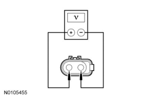
- Ignition ON.
- Check the voltage on the meter.
- Is the voltage greater than 10 volts?
Yes
INSTALL a new wheel speed sensor. REFER to Wheel Speed Sensor - Front Wheel Speed Sensor - Front or Wheel Speed Sensor - Rear Wheel Speed Sensor - Rear. CLEAR the DTCs. REPEAT the self-test.
No
GO to E10.
-------------------------------------------------
E10 CHECK THE WHEEL SPEED SENSOR CIRCUITS FOR AN OPEN
NOTE: Both circuits must be checked for each DTC.
- Ignition OFF.
- Disconnect: Suspect Wheel Speed Sensor (if not previously disconnected).
- Disconnect: ABS Module C135.
- Measure the resistance between the ABS module connector, harness side and the suspect wheel speed sensor connector, harness side as indicated in the following chart:
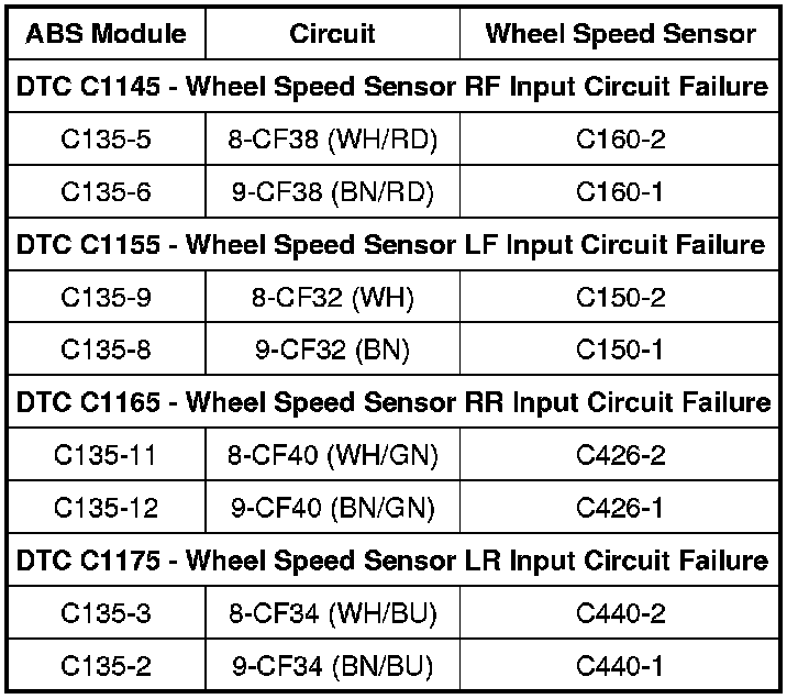
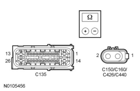
- Are the resistances less than 5 ohms?
Yes
GO to E11.
No
REPAIR the affected circuit(s). CLEAR the DTCs. REPEAT the self-test.
-------------------------------------------------
E11 CHECK FOR CORRECT ABS MODULE OPERATION
- Check ABS module C135 for:
- corrosion.
- pushed-out pins.
- spread terminals.
- Connect: Suspect Wheel Speed Sensor.
- Connect: ABS Module C135.
- Make sure the connectors are fully seated, then operate the system and verify the concern is still present.
- Is the concern still present?
Yes
INSTALL a new ABS module. REFER to Anti-Lock Brake System (ABS) Module Service and Repair. CLEAR the DTCs. REPEAT the self-test.
No
The system is operating correctly at this time. The concern may have been caused by a loose or corroded connector. CLEAR the DTCs. REPEAT the self-test.
-------------------------------------------------