Pinpoint Test A: The Control Illumination Is Inoperative
Instrument Cluster and Panel Illumination
Pinpoint Tests
Pinpoint Test A: The Control Illumination Is Inoperative
Refer to wiring Diagram Set 71, Cluster and Panel Illumination for schematic and connector information. Diagrams By Number
Normal Operation
When the headlamp switch is in the PARKING LAMPS or HEADLAMPS ON position, ground is supplied to the parking lamp relay coil through the Smart Junction Box (SJB). The parking lamp relay provides switched voltage to the instrument panel dimmer switch on circuit CBP01 (BU) from the SJB. The instrument panel dimmer switch provides a variable voltage to the IC and panel switches on circuit VLN18 (BU/WH).
This pinpoint test is intended to diagnose the following:
- Fuse(s)
- Wiring, terminals or connectors
- Instrument panel dimmer switch
PINPOINT TEST A: THE CONTROL ILLUMINATION IS INOPERATIVE
NOTICE: Use the correct probe adapter(s) when making measurements. Failure to use the correct probe adapter(s) may damage the connector.
-------------------------------------------------
A1 CHECK THE PARKING LAMPS OPERATION
- Place the headlamp switch in the PARKING LAMPS ON position.
- Are the parking lamps illuminated?
Yes
GO to A2.
No
REFER to Lighting and Horns. Testing and Inspection
-------------------------------------------------
A2 CHECK CIRCUIT CBP01 (BU) FOR AN OPEN
- Disconnect: Instrument Panel Dimmer Switch C2065.
- Place the headlamp switch in the PARKING LAMPS ON position.
- Measure the voltage between the instrument panel dimmer switch C2065-6, circuit CBP01 (BU), harness side and ground.
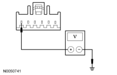
- Is the voltage greater than 10 volts?
Yes
GO to A3.
No
VERIFY the SJB fuse 1 (5A) is OK. If OK, REPAIR the circuit. TEST the system for normal operation. If not OK, REFER to the Wiring Diagrams to identify the possible causes of the circuit short.
-------------------------------------------------
A3 CHECK THE INSTRUMENT PANEL DIMMER SWITCH
- Connect a fused jumper wire between the instrument panel dimmer switch C2065-6, circuit CBP01 (BU), harness side and the instrument panel dimmer switch C2065-1, circuit VLN18 (BU/WH), harness side.
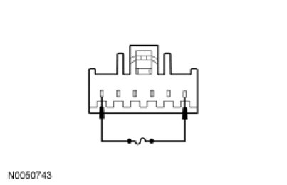
- Does the control illumination operate?
Yes
INSTALL a new instrument panel dimmer switch. REFER to Instrument Panel Dimmer Switch Service and Repair. TEST the system for normal operation.
No
REPAIR circuit VLN18 (BU/WH). TEST the system for normal operation.
-------------------------------------------------