Pinpoint Test H: The Autolamps Are On Continuously
Autolamps
Pinpoint Tests
Pinpoint Test H: The Autolamps Are On Continuously
Refer to Wiring Diagram Set 85, Headlamps/Autolamps for schematic and connector information. Diagrams By Number
Normal Operation
The Smart Junction Box (SJB) sends a reference signal to the headlamp switch through circuit CLF19 (VT/GN) and a signal to the light sensor through circuit VLF14 (BU/BN). Ground for the light sensor is provided through circuit GD115 (BK/GY).
When the headlamp switch is placed in the AUTOLAMPS ON position, the voltage signal is routed to ground. When the SJB detects the headlamp switch in the AUTOLAMPS ON position, the SJB monitors the light sensor input. The light sensor determines the amount of light based on the input received from the ambient lighting conditions. When the ambient level has reached a point (determined by the internal programming of the SJB), the SJB provides voltage to the headlamps, parking and license plate lamps.
The SJB also monitors the windshield wiper motor status by sending a voltage reference signal to the wiper motor through circuit CRW01 (WH). When the windshield is wiper is on (except during a mist wipe or while the wipers are on to clear washer fluid during a wash condition), the wiper motor grounds circuit CRW01 (WH) to indicate to the SJB that the wipers are on.
B1696-B2008:

This pinpoint test is intended to diagnose the following:
- Wiring, terminals or connectors
- Light sensor
- Headlamp switch
- Windshield wiper motor
- SJB
PINPOINT TEST H: THE AUTOLAMPS ARE ON CONTINUOUSLY
NOTICE: Use the correct probe adapter(s) when making measurements. Failure to use the correct probe adapter(s) may damage the connector.
-------------------------------------------------
H1 CHECK THE SJB AUTOLAMP ON REQUEST PID
- Ignition ON.
- Enter the following diagnostic mode on the scan tool: SJB DataLogger.
- NOTE: Make sure the headlamp switch is in the OFF position when monitoring the PID.
- Monitor the SJB headlamp switch PID (HDLMP_AUT_CKT).
- Does the PID indicate ON?
Yes
GO to H2.
No
GO to H5.
-------------------------------------------------
H2 CHECK THE HEADLAMP SWITCH
- Ignition OFF.
- Disconnect: Headlamp Switch C205.
- Carry out the headlamp switch component test.
- Is the headlamp switch OK?
Yes
GO to H3.
No
INSTALL a new headlamp switch. REFER to Headlamp Switch Service and Repair. CLEAR the DTCs. REPEAT the self-test.
-------------------------------------------------
H3 CHECK THE AUTOLAMPS REQUEST INPUT CIRCUIT FOR A SHORT TO GROUND
- Disconnect: SJB C2280b.
- Measure the resistance between the headlamp switch C205-9, circuit CLF19 (VT/GN), harness side and ground.
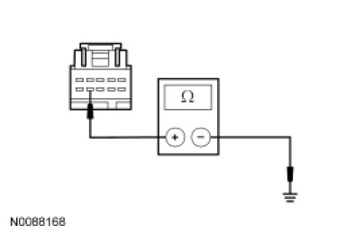
- Is the resistance greater than 10,000 ohms?
Yes
GO to H4.
No
REPAIR circuit CLF19 (VT/GN) for a short to ground. CLEAR the DTCs. REPEAT the self-test.
-------------------------------------------------
H4 CHECK THE AUTOLAMPS REQUEST INPUT CIRCUIT FOR AN OPEN
- Measure the resistance between the headlamp switch C205-9, circuit CLF19 (VT/GN), harness side and the SJB C2280b-50, circuit CLF19 (VT/GN), harness side.
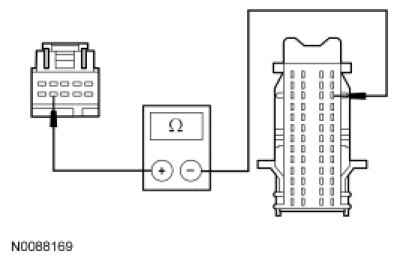
- Is the resistance less than 5 ohms?
Yes
GO to H15.
No
REPAIR circuit CLF19 (VT/GN) for an open. CLEAR the DTCs. REPEAT the self-test.
-------------------------------------------------
H5 USE THE RECORDED DTCs FROM THE SJB SELF-TEST
- Check the recorded results from the SJB self-test.
- Is DTC B2008, B1791 or B1793 present?
Yes
For DTC B2008, GO to H7.
For DTC B1791, GO to H9.
For DTC B1793, GO to H13.
No
GO to H6.
-------------------------------------------------
H6 CHECK FOR VOLTAGE TO THE LIGHT SENSOR (NO DTC)
- Ignition OFF.
- Disconnect: Light Sensor C286 or C287.
- Ignition ON.
- Place the headlamp switch in the AUTOLAMPS ON position.
- For vehicles with automatic temperature control, measure the voltage between the light sensor C286-2, circuit VLF14 (BU/BN), harness side and ground.

- For vehicles with manual temperature control, measure the voltage between the light sensor C287-A, circuit VLF14 (BU/BN), harness side and ground.
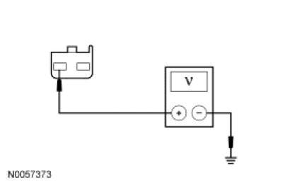
- Is the voltage approximately 5 volts?
Yes
INSTALL a new light sensor. REFER to Light Sensor Service and Repair. CLEAR the DTCs. REPEAT the self-test.
No
GO to H15.
-------------------------------------------------
H7 CHECK THE WINDSHIELD WIPER MOTOR
- Ignition ON.
- Disconnect: Windshield Wiper Motor C1552.
- Ignition OFF.
- Enter the following diagnostic mode on the scan tool: SJB Self-Test.
- Repeat the SJB self-test.
- Is DTC B2008 still present?
Yes
GO to H8.
No
INSTALL a new windshield wiper motor. TEST the system for normal operation.
-------------------------------------------------
H8 CHECK WIPERS ON INPUT CIRCUIT FOR A SHORT TO GROUND
- Ignition OFF.
- Disconnect: SJB C2280f.
- Measure the resistance between the windshield wiper motor C1552-2, circuit CRW01 (WH), harness side and ground.
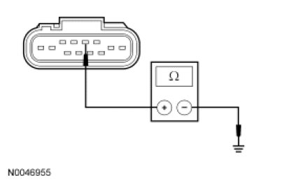
- Is the resistance greater than 10,000 ohms?
Yes
GO to H15.
No
REPAIR circuit CRW01 (WH) for a short to ground. CLEAR the DTCs. REPEAT the self-test.
-------------------------------------------------
H9 CHECK FOR VOLTAGE TO THE LIGHT SENSOR (DTC B1791)
- Ignition OFF.
- Disconnect: Light Sensor C286 or C287.
- Ignition ON.
- Place the headlamp switch in the AUTOLAMPS ON position.
- On vehicles with automatic temperature control, measure the voltage between the light sensor C286-2, circuit VLF14 (BU/BN), harness side and ground.
- On vehicles with manual climate control, measure the voltage between the light sensor C287-A, circuit VLF14 (BU/BN), harness side and ground.
- Is the voltage approximately 5 volts?
Yes
GO to H12.
No
GO to H10.
-------------------------------------------------
H10 CHECK THE LIGHT SENSOR INPUT CIRCUIT FOR A SHORT TO VOLTAGE
- Ignition OFF.
- Disconnect: SJB C2280b.
- Ignition ON.
- On vehicles with automatic temperature control, measure the voltage between the light sensor C286-2, circuit VLF14 (BU/BN), harness side and ground.
- On vehicles with manual climate control, measure the voltage between the light sensor C287-A, circuit VLF14 (BU/BN), harness side and ground.
- Is any voltage present?
Yes
REPAIR circuit VLF14 (BU/BN) for a short to voltage. CLEAR the DTCs. REPEAT the self-test.
No
GO to H11.
-------------------------------------------------
H11 CHECK THE LIGHT SENSOR INPUT CIRCUIT FOR AN OPEN
- Ignition OFF.
- On vehicles with automatic temperature control, measure the resistance between the light sensor C286-2, circuit VLF14 (BU/BN), harness side and the SJB C2280b-46, circuit VLF14 (BU/BN), harness side.

- On vehicles with manual climate control, measure the resistance between the light sensor C287-A, circuit VLF14 (BU/BN), harness side and the SJB C2280b-46, circuit VLF14 (BU/BN), harness side.
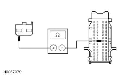
- Is the resistance less than 5 ohms?
Yes
GO to H15.
No
REPAIR circuit VLF14 (BU/BN) for an open. CLEAR the DTCs. REPEAT the self-test.
-------------------------------------------------
H12 CHECK FOR VOLTAGE TO THE LIGHT SENSOR USING THE CONNECTOR GROUND
- Ignition OFF.
- On vehicles with automatic temperature control, measure the voltage between the light sensor C286-2, circuit VLF14 (BU/BN), harness side and the light sensor C286-4, circuit GD115 (BK/GY), harness side.
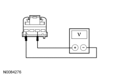
- On vehicles with manual climate control, measure the voltage between the light sensor C287-A, circuit VLF14 (BU/BN), harness side and the light sensor C287-B, circuit GD115 (BK/GY), harness side.
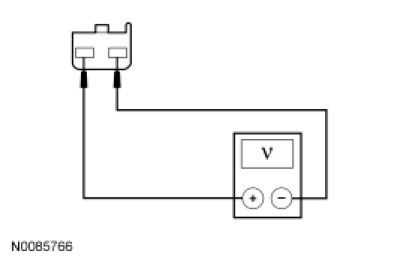
- Is the voltage greater than 10 volts?
Yes
INSTALL a new light sensor. REFER to Light Sensor Service and Repair. CLEAR the DTCs. REPEAT the self-test.
No
REPAIR circuit GD115 (BK/GY) for an open. CLEAR the DTCs. REPEAT the self-test.
-------------------------------------------------
H13 CHECK FOR VOLTAGE TO THE LIGHT SENSOR (DTC B1793)
- Ignition OFF.
- Disconnect: Light Sensor C286 or C287.
- Ignition ON.
- Place the headlamp switch in the AUTOLAMPS ON position.
- On vehicles with automatic temperature control, measure the voltage between the light sensor C286-2, circuit VLF14 (BU/BN), harness side and ground.
- On vehicles with manual temperature control, measure the voltage between the light sensor C287-A, circuit VLF14 (BU/BN), harness side and ground.
- Is the voltage approximately 5 volts?
Yes
INSTALL a new light sensor. REFER to Light Sensor Service and Repair. CLEAR the DTCs. REPEAT the self-test.
No
GO to H14.
-------------------------------------------------
H14 CHECK THE LIGHT SENSOR INPUT CIRCUIT FOR A SHORT TO GROUND
- Ignition OFF.
- Disconnect: SJB C2280b.
- On vehicles with automatic temperature control, measure the resistance between the light sensor C286-2, circuit VLF14 (BU/BN), harness side and ground.
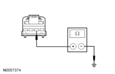
- On vehicles with manual temperature control, measure the resistance between the light sensor C287-A, circuit VLF14 (BU/BN), harness side and ground.
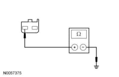
- Is the resistance greater than 10,000 ohms?
Yes
GO to H15.
No
REPAIR circuit VLF14 (BU/BN) for a short to ground. CLEAR the DTCs. REPEAT the self-test.
-------------------------------------------------
H15 CHECK FOR CORRECT SJB OPERATION
- Disconnect all the SJB connectors.
- Check for:
- corrosion
- damaged pins
- pushed-out pins
- Connect all the SJB connectors and make sure they seat correctly.
- Operate the system and verify the concern is still present.
- Is the concern still present?
Yes
INSTALL a new SJB. TEST the system for normal operation.
No
The system is operating correctly at this time. The concern may have been caused by a loose or corroded connector. CLEAR the DTCs. REPEAT the self-test.
-------------------------------------------------