Pinpoint Test J: One Or More Stoplamps Are Inoperative
Stoplamps
Pinpoint Tests
Pinpoint Test J: One Or More Stoplamps Are Inoperative
Refer to Wiring Diagram Set 90, Turn Signal/Stop/Hazard Lamps for schematic and connector information. Diagrams By Number
Normal Operation
When the brake pedal is applied, the stoplamp switch routes voltage to the Smart Junction Box (SJB) and the high mounted stoplamp through circuit CCB08 (VT/WH).
When the SJB detects the brake pedal is applied, the SJB provides voltage to the LH and RH rear stoplamps through circuits CLS18 (GY/BN) and CLS19 (VT/OG).
Ground for the LH and RH rear stoplamps is provided through circuits GD149 (BK/GY) and GD151 (BK/GN). Ground for the high mounted stoplamp is provided through circuit GD149 (BK/GY).
B106E-B2047:
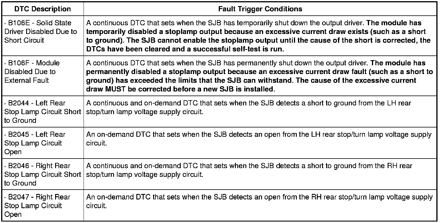
This pinpoint test is intended to diagnose the following:
- Wiring, terminals or connectors
- Bulb holder
- High mounted stoplamp
- SJB
PINPOINT TEST J: ONE OR MORE STOPLAMPS ARE INOPERATIVE
NOTICE: Use the correct probe adapter(s) when making measurements. Failure to use the correct probe adapter(s) may damage the connector.
NOTE: The battery ground cable must be disconnected for accurate test results when checking ground circuits for continuity to ground.
-------------------------------------------------
J1 DETERMINE THE INOPERATIVE STOPLAMP
- Ignition OFF.
- Apply the brake pedal and observe the stoplamps.
- Are all the stoplamps inoperative?
Yes
Go To Pinpoint Test I. Pinpoint Test I: All The Stoplamps Are Inoperative
No
For the high mounted stoplamp, GO to J2.
If both sides (LH and RH rear stoplamps) are inoperative, VERIFY the SJB fuse 6 (20A) is OK. If OK, GO to J4. If not OK, REFER to the Wiring Diagrams to identify the possible causes of the circuit short.
If only one side (the LH or RH rear stoplamp) is inoperative, GO to J5.
-------------------------------------------------
J2 CHECK FOR VOLTAGE TO HIGH MOUNTED STOPLAMP
- Disconnect: High Mounted Stoplamp C904.
- While applying the brake pedal, measure the voltage between the high mounted stoplamp C904-1, circuit CCB08 (VT/WH), harness side and ground.
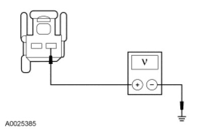
- Is the voltage greater than 10 volts?
Yes
GO to J3.
No
REPAIR the circuit. TEST the system for normal operation.
-------------------------------------------------
J3 CHECK FOR VOLTAGE TO THE HIGH MOUNTED STOPLAMP USING THE CONNECTOR GROUND
- Measure the voltage between the high mounted stoplamp C904-1, circuit CCB08 (VT/WH), harness side and the high mounted stoplamp C904-2, circuit GD149 (BK/GY), harness side.
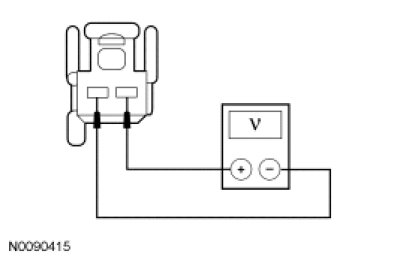
- Is the voltage greater than 10 volts?
Yes
INSTALL a new high mounted stoplamp. TEST the system for normal operation.
No
REPAIR circuit GD149 (BK/GY) for an open. TEST the system for normal operation.
-------------------------------------------------
J4 CHECK FOR VOLTAGE TO THE SJB
- Disconnect: SJB C2280b.
- While applying the brake pedal, measure the voltage between the SJB C2280b-40, circuit CCB08 (VT/WH), harness side and ground.

- Is the voltage greater than 10 volts?
Yes
GO to J11.
No
REPAIR the circuit. CLEAR the DTCs. REPEAT the self-test.
-------------------------------------------------
J5 USE THE RECORDED DTCs FROM THE SJB SELF-TEST
- Check the recorded results from the SJB self-test.
- Is DTC B2045 or DTC B2047 present?
Yes
GO to J8.
No
GO to J6.
-------------------------------------------------
J6 ISOLATE THE BULB HOLDER FOR A SHORT TO GROUND
- Disconnect: Inoperative Rear Lamp.
- Ignition ON.
- Enter the following diagnostic mode on the scan tool: SJB Self-Test.
- Clear the DTCs and repeat the self-test (required to enable the stoplamp output driver if DTC B106E is present).
- While applying the brake pedal, measure the voltage between the LH rear lamp C412-3, circuit CLS18 (GY/BN), harness side and ground; or between the RH rear lamp C415-3, circuit CLS19 (VT/OG), harness side and ground.
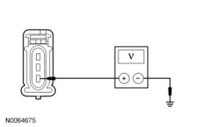
- Is the voltage greater than 10 volts?
Yes
INSTALL a new bulb holder. TEST the system for normal operation.
No
GO to J7.
-------------------------------------------------
J7 CHECK THE SJB STOPLAMP OUTPUT CIRCUIT FOR A SHORT TO GROUND
- Ignition OFF.
- Disconnect: Trailer Tow Stop/Turn Relays.
- Disconnect: SJB C2280d.
- Measure the resistance between the SJB C2280d-25, circuit CLS18 (GY/BN), harness side and ground; or between the SJB C2280d-26, circuit CLS19 (VT/OG), harness side and ground.
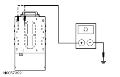
- Is the resistance greater than 10,000 ohms?
Yes
GO to J11.
No
REPAIR the circuit in question for a short to ground. After the repair:
If no DTCs are present, TEST the system for normal operation.
If DTC B106E is present, CLEAR the DTCs and REPEAT the self-test (required to enable the stoplamp output driver if DTC B106E is present). TEST the system for normal operation.
If DTC B106F is present, INSTALL a new SJB. TEST the system for normal operation.
-------------------------------------------------
J8 CHECK FOR VOLTAGE TO THE INOPERATIVE STOPLAMP
- Disconnect: Inoperative Rear Lamp.
- While applying the brake pedal, measure the voltage between the LH rear lamp C412-3, circuit CLS18 (GY/BN), harness side and ground; or between the RH rear lamp C415-3, circuit CLS19 (VT/OG), harness side and ground.
- Is the voltage greater than 10 volts?
Yes
GO to J9.
No
GO to J10.
-------------------------------------------------
J9 CHECK FOR VOLTAGE TO THE INOPERATIVE STOPLAMP USING THE CONNECTOR GROUND
- Measure the voltage between the LH rear lamp C412-3, circuit CLS18 (GY/BN), harness side and the LH rear lamp C412-1, circuit GD149 (BK/GY), harness side; or between the RH rear lamp C415-3, circuit CLS19 (VT/OG), harness side and the RH rear lamp C415-1, circuit GD151 (BK/GN), harness side.
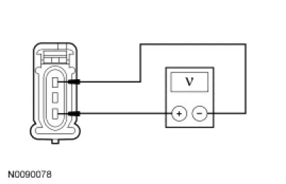
- Is the voltage greater than 10 volts?
Yes
INSTALL a new bulb holder. CLEAR the DTCs. REPEAT the self-test.
No
REPAIR circuit GD149 (BK/GY) (LH rear stoplamp) or circuit GD151 (BK/GN) (RH rear stoplamp) for an open. TEST the system for normal operation.
-------------------------------------------------
J10 CHECK THE SJB STOPLAMP OUTPUT CIRCUIT FOR AN OPEN
- Disconnect: SJB C2280d.
- Measure the resistance between the LH rear lamp C412-3, circuit CLS18 (GY/BN), harness side and the SJB C2280d-25, circuit CLS18 (GY/BN), harness side; or between the RH rear lamp C415-3, circuit CLS19 (VT/OG), harness side and the SJB C2280d-26, circuit CLS19 (VT/OG), harness side.
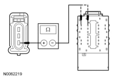
- Is the resistance less than 5 ohms?
Yes
GO to J11.
No
REPAIR circuit CLS18 (GY/BN) (LH rear stoplamp) or circuit CLS19 (VT/OG) (RH rear stoplamp) for an open. CLEAR the DTCs. REPEAT the self-test.
-------------------------------------------------
J11 CHECK FOR CORRECT SJB OPERATION
- Disconnect all the SJB connectors.
- Check for:
- corrosion
- damaged pins
- pushed-out pins
- Connect all the SJB connectors and make sure they seat correctly.
- Operate the system and verify the concern is still present.
- Is the concern still present?
Yes
INSTALL a new SJB. TEST the system for normal operation.
No
The system is operating correctly at this time. The concern may have been caused by a loose or corroded connector. CLEAR the DTCs. REPEAT the self-test.
-------------------------------------------------