Instrument Cluster (IC)
Instrument Cluster (IC)
Edge

MKX


Removal
All vehicles
NOTE: When installing a new Instrument Cluster (IC), it is necessary to upload the module configuration to the scan tool.
1. Disconnect the battery.
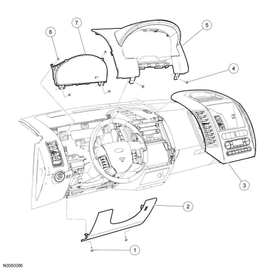
2. Remove the 2 screws and the lower steering column cover.
- If equipped, disconnect the ambient air temperature sensor air hose and electrical connector.
3. Tilt the steering column to the lowest position.
Edge
4. NOTE: The instrument panel center finish panel is held in place by spring clips located on the finish panel.
Pull the instrument panel center finish panel straight out to release the retaining tabs and position aside.
All vehicles
5. Release the 4 locating tabs on the IC finish panel gap reveal from the upper steering column cover.
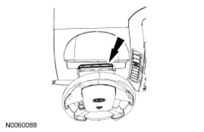
6. NOTE: The upper section of the IC finish panel is held in place by spring clips located on the finish panel.
Remove the 2 screws and the IC finish panel.
- If equipped, disconnect the power liftgate switch electrical connector.
7. Remove the 4 screws and the IC.
- Disconnect the electrical connector.
Installation
All vehicles
1. Position the IC, connect the electrical connector and install the 4 screws.
2. NOTE: The upper section of the IC finish panel is held in place by spring clips located on the finish panel.
Position the IC finish panel, connect the power liftgate switch electrical connector (if equipped) and install the 2 screws.
3. Install the 4 locating tabs on the IC finish panel reveal into the upper steering column cover.
Edge
4. Position and install the instrument panel center finish panel.
All vehicles
5. Position the lower steering column cover, connect the ambient air temperature sensor hose and electrical connector (if equipped) and install the 2 screws.
6. Connect the battery.
7. NOTE: If a new IC is installed, download the configuration from the scan tool into the new IC. For additional information, refer to the Programmable Module Installation (PMI) in Information Bus. Programming and Relearning
NOTE: If a new IC is installed, the IC and the PCM require a parameter reset to allow the IC and the PCM to recognize each other. Failure to carry out the parameter reset to the IC and the PCM may result in a no start condition.
NOTE: The vehicle's integrated keys (or standard Passive Anti-Theft System (PATS) keys) must be programmed to the new IC.
Carry out the parameter reset and key programming procedure. Programming and Relearning
8. Clear all IC and PCM DTCs.