Pinpoint Test D: DTCs C1222, C1233, C1234, C1235 And C1236
Anti-Lock Control
Pinpoint Tests
Pinpoint Test D: DTCs C1222, C1233, C1234, C1235 and C1236
Refer to Wiring Diagram Set 42, Vehicle Dynamic Systems for schematic and connector information. Diagrams By Number
Normal Operation
The wheel speed sensors generate a square wave signal that is sent to the ABS module. The wheel speed sensor circuitry connects to the ABS module through 2 wires and a connector at each wheel speed sensor. When the ignition is turned to the RUN position, the ABS module carries out a self-test to determine if the sensors are functional. Voltage is supplied to the active wheel speed sensors from the ABS module. The wheel speed sensor ground is supplied by the ABS module.
Wheel speed sensor DTCs will automatically clear when a successful test drive is carried out. A successful test drive should include speeds above 32 km/h (20 mph) and at least one ABS stop.
C1222-C1236:
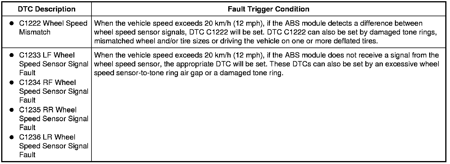
This pinpoint test is intended to diagnose the following:
- Mismatched tire sizes
- Wheel speed sensor tone ring
- Wheel speed sensor
- ABS module
PINPOINT TEST D: DTC C1222, C1233, C1234, C1235 OR C1236
NOTICE: Use the Flex Probe Kit for all test connections to prevent damage to the wiring terminals. Do not use standard multi-meter probes.
-------------------------------------------------
D1 RETRIEVE ABS MODULE DTCs
- Connect the scan tool.
- Ignition ON.
- Enter the following diagnostic mode on the scan tool: Self Test - All CMDTCs.
- Retrieve and record all ABS module DTCs.
- Is DTC C1145, C1155, C1165 or C1175 present?
Yes
Go To Pinpoint Test C. Pinpoint Test C: DTCs C1145, C1155, C1165 And C1175
No
If DTC C1222 is present, GO to D2.
If DTC C1233, C1234, C1235 or C1236 is present, GO to D3.
For all other ABS module DTCs, GO to the ABS Module DTC Chart. ABS Module DTC Chart
-------------------------------------------------
D2 CHECK FOR CORRECT TIRE SIZE AND AIR PRESSURE
- Make sure all tire sizes are correct and matching.
- Make sure all tire pressures are correct.
- Clear the DTCs, drive the vehicle and carry out the self-test.
- Is DTC C1222 still present?
Yes
GO to D3.
No
The system is operating correctly at this time. TEST DRIVE the vehicle above 32 km/h (20 mph) and CARRY OUT at least one ABS stop.
-------------------------------------------------
D3 CHECK THE ABS HARNESS AND MODULE FOR WATER INTRUSION
- Ignition OFF.
- Disconnect: ABS Module C135.
- Inspect the ABS module connector and module for water intrusion.
- Is there any evidence of water entry?
Yes
CLEAN the connector and dry it out with low pressure compressed air. INSPECT for evidence of water entry and repair as necessary. TEST DRIVE the vehicle above 32 km/h (20 mph) and CARRY OUT at least one ABS stop.
No
If the Active Wheel Speed Sensor Tester is available, GO to D4.
If the Active Wheel Speed Sensor Tester is not available, GO to D7.
-------------------------------------------------
D4 CHECK THE ABS MODULE OUTPUT USING THE ACTIVE WHEEL SPEED SENSOR TESTER
- Connect: ABS Module C135.
- Disconnect: Suspect Wheel Speed Sensor.
- Connect the Active Wheel Speed Sensor Tester to the wheel speed sensor connectors.
- Ignition ON.
- Select the correct system polarity on the Active Wheel Speed Sensor Tester and turn the power switch to the ON position.
- Is the module output LED illuminated?
Yes
GO to D6.
No
GO to D5.
-------------------------------------------------
D5 CHECK THE WHEEL SPEED SENSOR CIRCUITS FOR AN OPEN
NOTE: Both circuits must be checked for each DTC.
- Ignition OFF.
- Disconnect: ABS Module C135.
- Measure the resistance between the ABS module connector, harness side and the suspect wheel speed sensor connector, harness side as indicated in the following chart:
DTC C1233-DTC C1236:
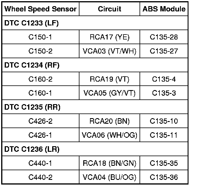
- Are the resistances less than 5 ohms?
Yes
GO to D8.
No
REPAIR the affected circuit(s). TEST DRIVE the vehicle above 32 km/h (20 mph) and CARRY OUT at least one ABS stop.
-------------------------------------------------
D6 CHECK THE WHEEL SPEED SENSOR OUTPUT WITH THE ACTIVE WHEEL SPEED SENSOR TESTER
- Raise the suspect wheel until it can spin freely. Refer to Maintenance/Service and Repair.
- While monitoring the Active Wheel Speed Sensor Tester, slowly spin the suspect wheel.
- Do the sensor output LEDs illuminate and flash and is the current overload LED not illuminated?
Yes
The system is operating correctly at this time. The concern may have been caused by a loose or corroded connector. TEST DRIVE the vehicle above 32 km/h (20 mph) and CARRY OUT at least one ABS stop.
No
If the current level LED is not illuminated and the sensor output LEDs do not illuminate or if the current level LED is illuminated red, INSTALL a new wheel speed sensor. For the front wheel speed sensor, REFER to Wheel Speed Sensor - Front Wheel Speed Sensor - Front. For the rear wheel speed sensor, REFER to Wheel Speed Sensor - Rear Wheel Speed Sensor - Rear. CLEAR the DTCs. REPEAT the self-test.
If the current level LED is not illuminated and the sensor output LEDs illuminate green but do not flash, INSPECT the wheel speed sensor tone ring and INSTALL new if necessary. If the tone ring is OK, INSTALL a new wheel speed sensor. REFER to Wheel Speed Sensor - Front Wheel Speed Sensor - Front or Wheel Speed Sensor - Rear Wheel Speed Sensor - Rear. TEST DRIVE the vehicle above 32 km/h (20 mph) and CARRY OUT at least one ABS stop.
-------------------------------------------------
D7 CHECK THE WHEEL SPEED SENSOR OUTPUT
- Connect: ABS Module C135.
- Disconnect: Suspect Wheel Speed Sensor.
- For DTC C1233 (LF):
- connect a fused jumper wire between LF wheel speed sensor C150-2, circuit VCA03 (VT/WH), harness side and LF wheel speed sensor C150 pin-2, component side.
- connect the automotive meter between LF wheel speed sensor C150-1, circuit RCA17 (YE), harness side and LF wheel speed sensor C150 pin-1, component side.
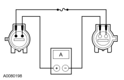
- For DTC C1234 (RF):
- connect a fused jumper wire between RF wheel speed sensor C160-1, circuit VCA05 (GY/VT), harness side and RF wheel speed sensor C160 pin-1, component side.
- connect the automotive meter between RF wheel speed sensor C160-2, circuit RCA19 (VT), harness side and RF wheel speed sensor C160 pin-2, component side.
- For DTC C1235 (RR):
- connect a fused jumper wire between RR wheel speed sensor C426-1, circuit VCA06 (WH/OG), harness side and RR wheel speed sensor C420 pin-1, component side.
- connect the automotive meter between RR wheel speed sensor C426-2, circuit RCA20 (BN), harness side and RR wheel speed sensor C420 pin-2, component side.
- For DTC C1236 (LR):
- connect a fused jumper wire between LR wheel speed sensor C440-2, circuit VCA04 (BU/OG), harness side and LF wheel speed sensor C440 pin-1, component side.
- connect the automotive meter between LR wheel speed sensor C440-1, circuit RCA18 (BN/GN), harness side and LF wheel speed sensor C440 pin-2, component side.
- Ignition ON.
- Measure the current while slightly rotating the wheel, using incremental turns.
- Does the wheel speed sensor output switch between the low state (4 to 8 mA) and the high state (12 to 16 mA)?
Yes
GO to D8.
No
INSTALL a new wheel speed sensor. REFER to Wheel Speed Sensor - Front Wheel Speed Sensor - Front or Wheel Speed Sensor - Rear Wheel Speed Sensor - Rear. TEST DRIVE the vehicle above 32 km/h (20 mph) and CARRY OUT at least one ABS stop.
-------------------------------------------------
D8 CHECK FOR CORRECT ABS MODULE OPERATION
- Ignition OFF.
- Disconnect: ABS C135.
- Check the connector for:
- corrosion.
- pushed-out pins.
- spread terminals.
- Connect: ABS C135.
- Make sure the ABS connector seats correctly.
- Test drive the vehicle above 32 km/h (20 mph), carry out at least one ABS stop and verify the concern is still present.
- Is the concern still present?
Yes
INSTALL a new ABS module. REFER to Anti-Lock Brake System (ABS) Module Service and Repair. TEST DRIVE the vehicle above 32 km/h (20 mph) and CARRY OUT at least one ABS stop.
No
The system is operating correctly at this time. The concern may have been caused by a loose or corroded connector. TEST DRIVE the vehicle above 32 km/h (20 mph) and CARRY OUT at least one ABS stop.
-------------------------------------------------