Shock Absorber Replacement (w/FE5)
Shock Absorber Replacement (w/FE5)
Removal Procedure
1. Raise the vehicle. Refer to Lifting and Jacking the Vehicle Service and Repair.
2. Remove the tire and wheel assembly. Refer to Tire and Wheel Removal and Installation (w RT2) Tire and Wheel Removal and Installation (w RT2)Tire and Wheel Removal and Installation (w/o RT2) Tire and Wheel Removal and Installation (w/o RT2).
3. Support the rear knuckle with a suitable hydraulic jack.
4. Remove the stabilizer shaft link from the lower control arm, if needed. Refer to Stabilizer Shaft Link Replacement (w/o FE4, FE5, FE6) Stabilizer Shaft Link Replacement (w/o FE4, FE5, FE6)Stabilizer Shaft Link Replacement (w FE4, FE5, FE6) Stabilizer Shaft Link Replacement (w FE4, FE5, FE6).
5. Remove the lower control arm bolt from the knuckle. Refer to Lower Control Arm Replacement Lower Control Arm Replacement.
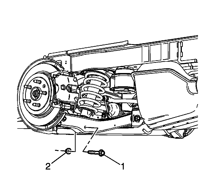
6. Remove the lower rear shock absorber nut (2) and bolt (1).
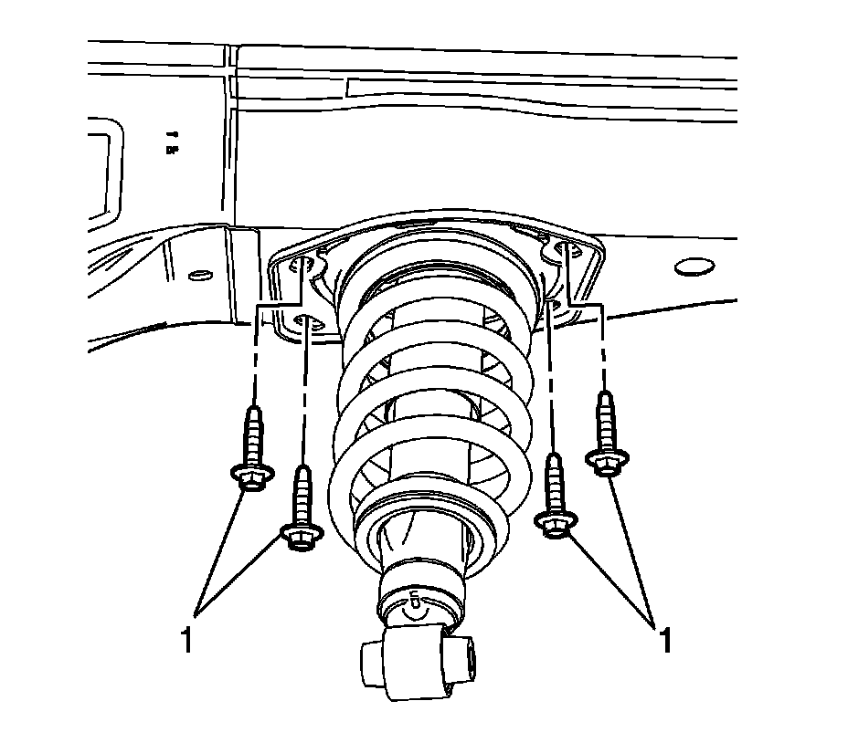
7. Remove the upper shock absorber bolts (1).
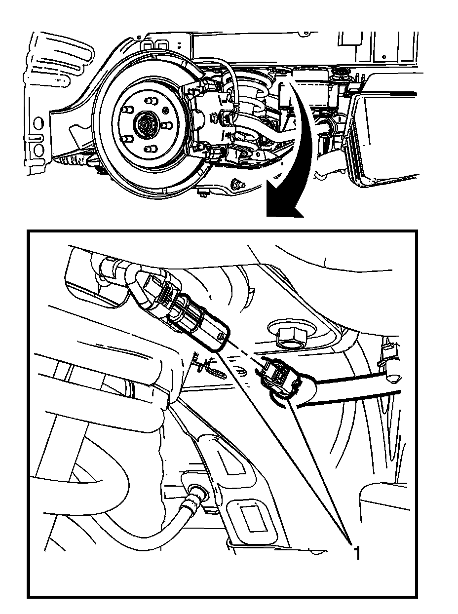
8. Lower the rear shock absorber assembly enough to disconnect the electrical connector (1) for the electronic suspension.
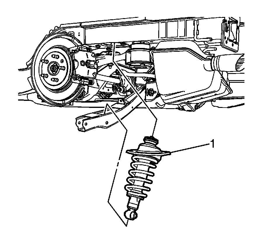
9. Remove the rear shock absorber assembly (1) from the vehicle.
Installation Procedure
1. Position the rear shock absorber assembly (1) in the vehicle.
Caution: Refer to Fastener Caution Fastener Caution.
2. Install the upper shock absorber bolts (1) and tighten the bolts to 58 Nm (43 lb ft).
3. Reconnect the electrical connector (1) for the electronic suspension.
4. If needed, use the hydraulic jack to raise the lower control arm and install the lower control arm bolt. Refer to Lower Control Arm Replacement Lower Control Arm Replacement.
5. Install the lower shock absorber bolt (1) and nut (2) and tighten to:
* First Pass: 80 Nm (59 lb ft)
* Final Pass: plus 120 degrees
6. Remove the hydraulic jack.
7. Install the stabilizer shaft link from the lower control arm, if needed. Refer to Stabilizer Shaft Link Replacement (w/o FE4, FE5, FE6) Stabilizer Shaft Link Replacement (w/o FE4, FE5, FE6)Stabilizer Shaft Link Replacement (w FE4, FE5, FE6) Stabilizer Shaft Link Replacement (w FE4, FE5, FE6).
8. Install the tire and wheel assembly. Refer to Tire and Wheel Removal and Installation (w RT2) Tire and Wheel Removal and Installation (w RT2)Tire and Wheel Removal and Installation (w/o RT2) Tire and Wheel Removal and Installation (w/o RT2).
9. Lower the vehicle.